Topic3:Verification and Test Verilog for Verification 。Testbench anatomy Behavioral modeling for Testbench 。Some examples Timing specification 。Delay model 。Timing verification 。Pipeline technology Design For Test(DFT) Test vs.Verification Build In Self Test (BIST) Scan and Boundary Scan 2021/1/13 ASIC Design,by Yan Bo 3
ASIC Design, by Yan Bo Topic3: Verification and Test Verilog for Verification • Testbench anatomy • Behavioral modeling for Testbench • Some examples Timing specification • Delay model • Timing verification • Pipeline technology Design For Test (DFT) Test vs. Verification Build In Self Test (BIST) Scan and Boundary Scan 2021/1/13 3
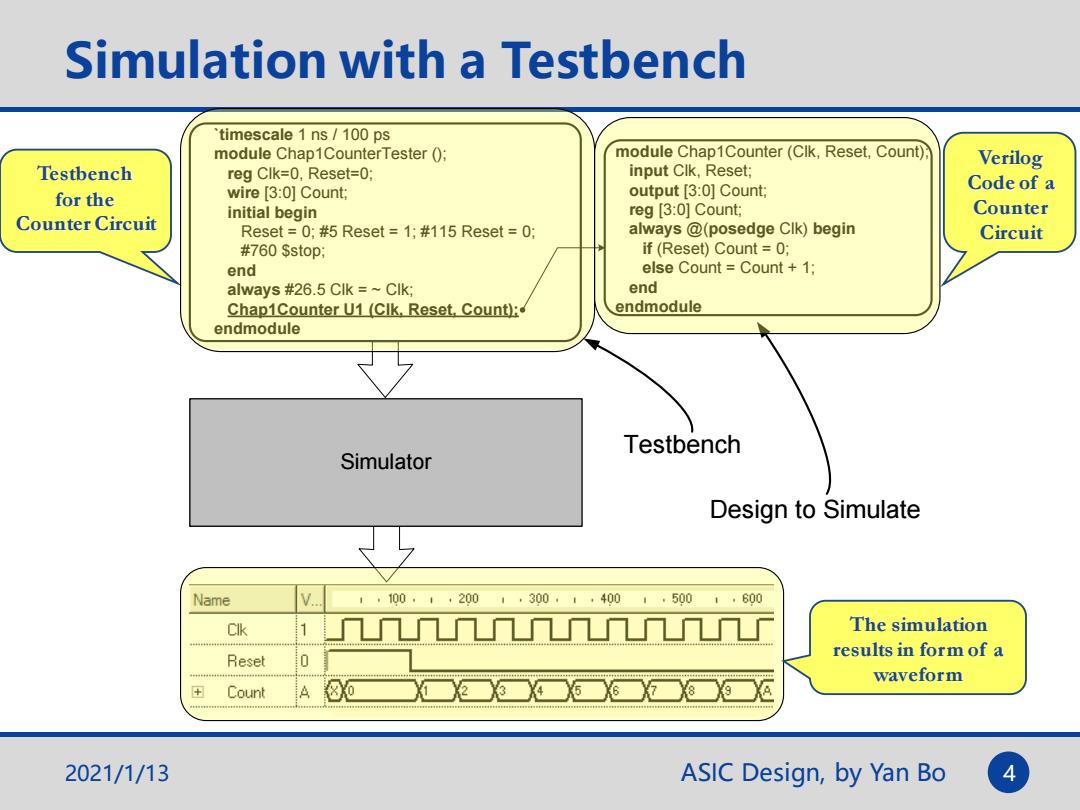
Simulation with a Testbench timescale 1 ns/100 ps module Chap1CounterTester ( module Chap1Counter(Clk,Reset,Count): input Clk,Reset: Verilog Testbench reg Clk=0,Reset=0; wire [3:0]Count; output [3:0]Count; Code of a for the Counter Circuit initial begin reg [3:0]Count; Counter Reset=0;#5 Reset=1;#115 Reset=0; always @(posedge Clk)begin Circuit #760 Sstop; if (Reset)Count 0; end else CountCount +1; always #26.5 Clk =Clk: end Chap1Counter U1 (CIk,Reset,Count); endmodule endmodule Testbench Simulator Design to Simulate Name 1,100.1·2001,300·1,4001.5001·600 Clk The simulation Reset results in form of a 0 waveform Count 80 3 2021/1/13 ASIC Design,by Yan Bo 4
ASIC Design, by Yan Bo Simulation with a Testbench Testbench for the Counter Circuit Verilog Code of a Counter Circuit `timescale 1 ns / 100 ps module Chap1CounterTester (); reg Clk=0, Reset=0; wire [3:0] Count; initial begin Reset = 0; #5 Reset = 1; #115 Reset = 0; #760 $stop; end always #26.5 Clk = ~ Clk; Chap1Counter U1 (Clk, Reset, Count); endmodule module Chap1Counter (Clk, Reset, Count); input Clk, Reset; output [3:0] Count; reg [3:0] Count; always @(posedge Clk) begin if (Reset) Count = 0; else Count = Count + 1; end endmodule Simulator Testbench Design to Simulate The simulation results in form of a waveform 2021/1/13 4
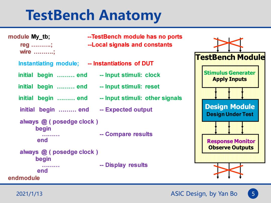
TestBench Anatomy module My_tb; --TestBench module has no ports reg.… --Local signals and constants 土 wire......... TestBench Module Instantiating module; -Instantiations of DUT initial begin .........end --Input stimuli:clock Stimulus Generater Apply Inputs initial begin .........end --Input stimuli:reset initial begin .........end --Input stimuli:other signals initial begin ........end --Expected output Design Module Design Under Test always @posedge clock begin --Compare results end Response Monitor Observe Outputs always @posedge clock begin -Display results end endmodule 2021/1/13 ASIC Design,by Yan Bo 5
ASIC Design, by Yan Bo TestBench Anatomy TestBench Module Design Module Stimulus Generater Apply Inputs Response Monitor Observe Outputs 2021/1/13 5 module My_tb; --TestBench module has no ports reg ……….; --Local signals and constants wire ……….; Instantiating module; -- Instantiations of DUT initial begin ……… end -- Input stimuli: clock initial begin ……… end -- Input stimuli: reset initial begin ……… end -- Input stimuli: other signals initial begin ……… end -- Expected output always @ ( posedge clock ) begin ……… -- Compare results end always @ ( posedge clock ) begin ……… -- Display results end endmodule Design Under Test
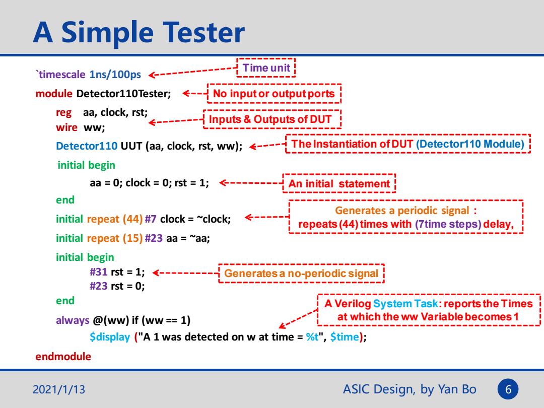
A Simple Tester Time unit timescale 1ns/100ps------- module Detector110Tester;--No inputor output ports reg aa,clock,rstiInputs&Outputs of DUT wire ww; Detector110 UUT (aa,clock,rst,ww);----The Instantiation ofDUT(Detector110 Module) initial begin aa =0;clock 0;rst =1;--------An initial statement end Generates a periodic signal initial repeat (44)#7 clock ~clock; ← repeats(44)times with(7time steps)delay, initial repeat (15)#23 aa ~aa; initial begin #31rst=1;<-------= Generates a no-periodic signal #23rst=0; end A Verilog System Task:reports the Times always @(ww)if (ww =1) at which the ww Variable becomes 1 Sdisplay ("A 1 was detected on w at time =%t",Stime); endmodule 2021/1/13 ASIC Design,by Yan Bo 6
ASIC Design, by Yan Bo A Simple Tester `timescale 1ns/100ps module Detector110Tester; reg aa, clock, rst; wire ww; Detector110 UUT (aa, clock, rst, ww); initial begin aa = 0; clock = 0; rst = 1; end initial repeat (44) #7 clock = ~clock; initial repeat (15) #23 aa = ~aa; initial begin #31 rst = 1; #23 rst = 0; end always @(ww) if (ww == 1) $display ("A 1 was detected on w at time = %t", $time); endmodule No input or output ports Inputs & Outputs of DUT The Instantiation of DUT (Detector110 Module) An initial statement Generates a periodic signal : repeats (44) times with (7time steps) delay, Generates a no-periodic signal A Verilog System Task: reports the Times at which the ww Variable becomes 1 Time unit 2021/1/13 6
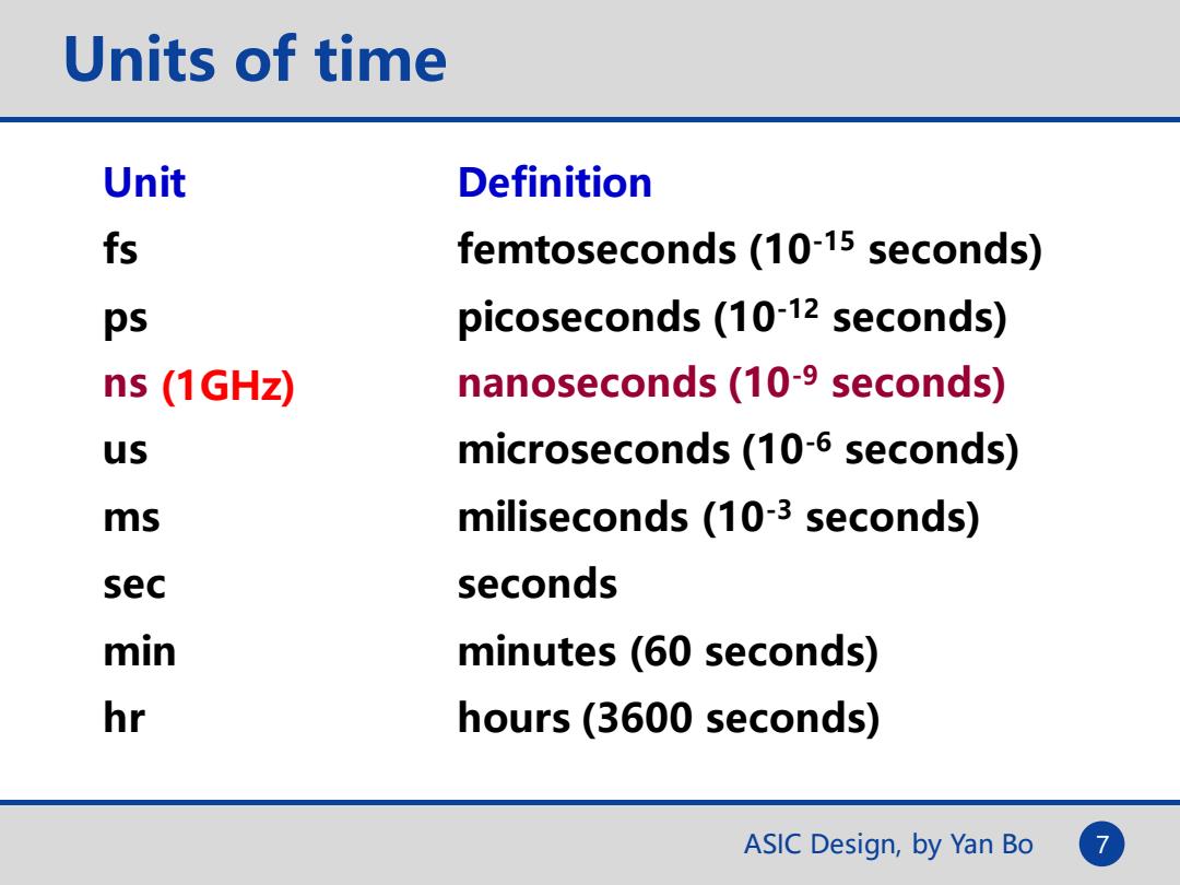
Units of time Unit Definition fs femtoseconds(10-15 seconds) ps picoseconds(10-12 seconds) ns (1GHz) nanoseconds(10-9 seconds) us microseconds(10-6 seconds) ms miliseconds (10-3 seconds) sec seconds min minutes(60 seconds) hr hours(3600 seconds) ASIC Design,by Yan Bo
ASIC Design, by Yan Bo 7 Units of time Unit Definition fs femtoseconds (10-15 seconds) ps picoseconds (10-12 seconds) ns nanoseconds (10-9 seconds) us microseconds (10-6 seconds) ms miliseconds (10-3 seconds) sec seconds min minutes (60 seconds) hr hours (3600 seconds) (1GHz)