Design of P-3623 Composite Slab Professor Shiming Chen College of Civil Engineering Tongji University
Design of P-3623 Composite Slab Professor : Shiming Chen College of Civil Engineering Tongji University
90 Bearing Capacity of Composite Slabs Bending resistance Ultimate limited Diagonal shear resistance state design Longitudinal shear resistance Serviceability limited Deflections state design
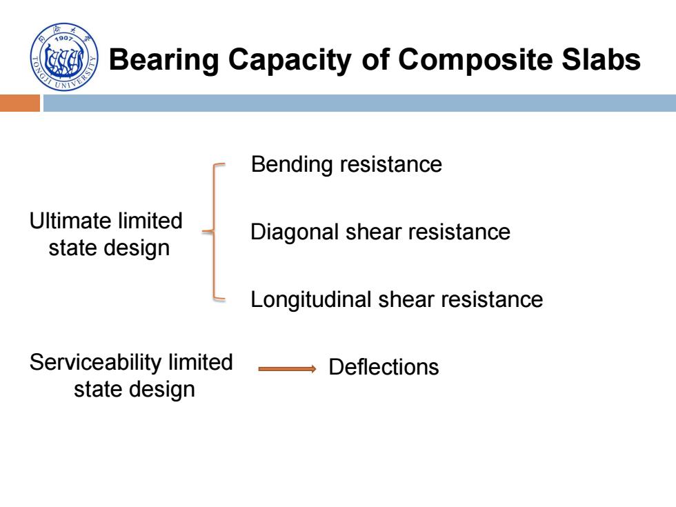
Bearing Capacity of Composite Slabs Ultimate limited state design Bending resistance Diagonal shear resistance Longitudinal shear resistance Serviceability limited state design Deflections
Design Example:P-3623 Composite Slab 1.Parameters of P-3623 composite slab 1000 305 140 Fig.1 Cross-section of P-3623 Steel deck: Thickness of the steel deck:t=0.76mm Steel: Area of the steel deck:A=950mm2 Yielding strength:f=230MPa Moment of inertia:/=441080mm4 Elastic modulus:Es=2.03 X 10⁵N/mm2 Composite slab: Concrete: Span length:L=1600mm Compressive strength:f=20.7MPa Width:b=1000mm Elastic modulus:E。=2.8×10⁴N/mm2
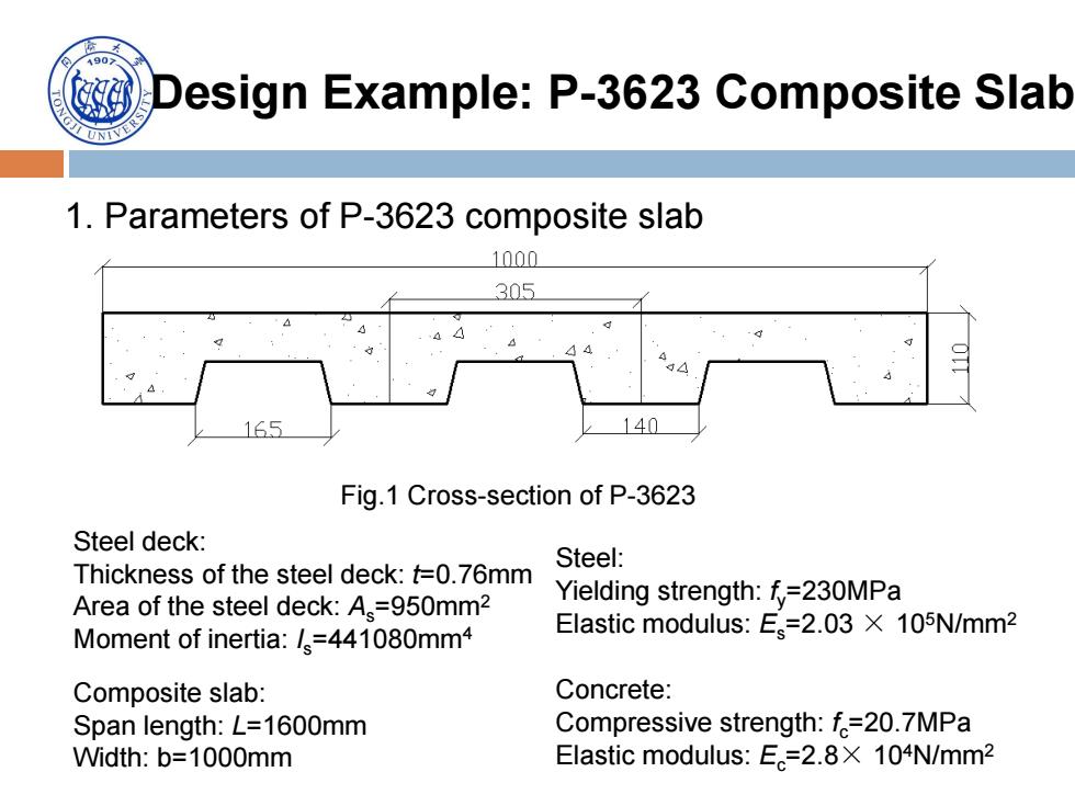
Design Example: P-3623 Composite Slab 1. Parameters of P-3623 composite slab Fig.1 Cross-section of P-3623 Steel deck: Thickness of the steel deck: t=0.76mm Area of the steel deck: As=950mm2 Moment of inertia: Is=441080mm4 Composite slab: Span length: L=1600mm Width: b=1000mm Steel: Yielding strength: fy=230MPa Elastic modulus: Es=2.03 × 10⁵N/mm2 Concrete: Compressive strength: fc=20.7MPa Elastic modulus: Ec=2.8× 10⁴N/mm2
90 Positive bending resistance Assume neutral axis lies in concrete slab above the steel deck fA,=fbx。 x-4-230x950 fb20.7×1000 =10.56mm<51mm Neutral axis does locate in concrete slab above the steel deck So,bending resistance is M,=xfbx.(h-x。/2)=0.8×20.7×1000×10.56×(84.5-10.56/2)=13.85kWm In midspan:M. The ultimate design load: qu= 8M_8x13.85=49.24kW/m2 b12 1×1.52
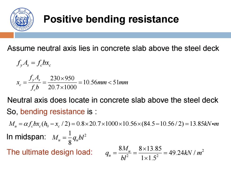
Positive bending resistance Assume neutral axis lies in concrete slab above the steel deck y s c c f A f bx 230 950 10.56 51 20.7 1000 y s c c f A x mm mm f b Neutral axis does locate in concrete slab above the steel deck So, bending resistance is : 0 ( / 2) 0.8 20.7 1000 10.56 (84.5 10.56/ 2) 13.85 M f bx h x kN m u c c c 1 2 8 In midspan: M q bl u u 2 2 2 8 8 13.85 49.24 / 1 1.5 u u M q kN m bl The ultimate design load:

Positive bending resistance As the slab span changes,the ultimate design load changes; The table below shows the ultimate design loads with different spans calculated from the bending resistance Table 1.The ultimate design loads L(mm) 1500 1650 1800 1950 2100 2250 2400 2550 2700 2850 3000 3150 3300 qu(kN/mm 49.24 40.70 34.20 29.14 2) 25.12 21.88 19.24 17.04 15.20 13.64 12.31 11.17 10.17
Positive bending resistance As the slab span changes, the ultimate design load changes; The table below shows the ultimate design loads with different spans calculated from the bending resistance L(mm) 1500 1650 1800 1950 2100 2250 2400 2550 2700 2850 3000 3150 3300 qu (kN/mm 2 ) 49.24 40.70 34.20 29.14 25.12 21.88 19.24 17.04 15.20 13.64 12.31 11.17 10.17 Table 1. The ultimate design loads