
442 DESIGN OF MACHINERY CHAPTER 9 my= din= Nin dout Nout (9.5a m7=±u=t (9.5b) din in Thus the velocity ratio and torque ratio can be computed from the number of teeth on the meshing gears,which are integers.Note that a minus sign implies an external gearset and a positive sign an internal gearset as shown in Figure 9-1.The gear ratio mG is always >I and can be expressed in terms of either the velocity ratio or torque ratio depending on Pitch circle which is larger than 1.Thus mG expresses the gear train's overall ratio independent of change in direction of rotation or of the direction of power flow through the train when Base circle operated either as a speed reducer or a speed increaser. mG=my or mG=T for mG21 (9.5c) STANDARD GEAR TEETH Standard,full-depth gear teeth have equal addenda on pinion and gear,with the dedendum being slightly larger for clearance.The standard (a)0=14.5° tooth dimensions are defined in terms of the diametral pitch.Table 9-1(p.441)shows the definitions of dimensions of standard,full-depth gear teeth as defined by the AGMA. and Figure 9-10 shows their shapes for three standard pressure angles.Figure 9-11 shows the actual sizes of 20pressure angle,standard,full-depth teeth from p=4 to 80. Note the inverse relationship between pa and tooth size.While there are no theoretical Pitch circle restrictions on the possible values of diametral pitch,a set of standard values is defined based on available gear cutting tools.These standard tooth sizes are shown in Table 9-2 Base circle in terms of diametral pitch and in Table 9-3 in terms of metric module. 9.4 INTERFERENCE AND UNDERCUTTING The involute tooth form is only defined outside of the base circle.In some cases,the de- (b)◆=20 dendum will be large enough to extend below the base circle.If so,then the portion of tooth below the base circle will not be an involute and will interfere with the tip of the tooth on the mating gear,which is an involute.If the gear is cut with a standard gear shaper or a"hob,"the cutting tool will also interfere with the portion of tooth below the base circle and will cut away the interfering material.This results in an undercut tooth as Pitch circle shown in Figure 9-12.This undercutting weakens the tooth by removing material at its root.The maximum moment and maximum shear from the tooth loaded as a cantilever beam both occur in this region.Severe undercutting will promote early tooth failure. Basd circle Interference and its attendant undercutting can be prevented simply by avoiding gears with too few teeth.If a gear has a large number of teeth,they will be small com- pared to its diameter.As the number of teeth is reduced for a fixed diameter gear,the teeth (C)0=25 must become larger.At some point,the dedendum will exceed the radial distance between the base circle and the pitch circle,and interference will occur. FIGURE 9-10 Table 9-4 shows the minimum number of teeth required to avoid undercutting AGMA full-depth tooth against a standard rack as a function of pressure angle.Table 9-5 shows the minimum profiles for three number of full-depth pinion teeth that can be used against a selection of full-depth gears pressure angles of various sizes (for=20).As the mating gear gets smaller,the pinion can have few- er teeth and still avoid interference

GEAR TRAINS 443 TABLE 9-2 Standard Diametral Pitches Coarse Fine 。 (pa<20) (pa220) 22 1 20 ”晶、 24 20 1.25 24 48 1.5 64 32 40 1.75 48 2 64 品 2.5 72 82 80 96 5 120 6 8 10 12 14 16 FIGURE 9-11 18 Actual tooth sizes for various diametral pitches Courtesy of Barber-Colman Co..Loves Park.IL Gear Base circle of gear Pitch circles Base circle of pinion Pinion Undercutting Interference Tooth below base circle ts not an involute FIGURE 9-12 Interference and undercutting of teeth below the base circle
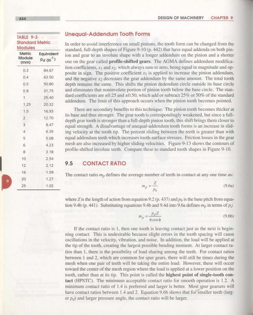
444 DESIGN OF MACHINERY CHAPTER 9 TABLE 9-3 Unequal-Addendum Tooth Forms Standard Metric In order to avoid interference on small pinions,the tooth form can be changed from the Modules standard.full-depth shapes of Figure 9-10(p.442)that have equal addenda on both pin- Metric Equivalent Module ion and gear to an involute shape with a longer addendum on the pinion and a shorter Pd (in) (mm) one on the gear called profile-shifted gears.The AGMA defines addendum modifica- 03 84.67 tion coefficients,xI and x2.which always sum to zero,being equal in magnitude and op posite in sign.The positive coefficient x is applied to increase the pinion addendum, 0.4 63.50 and the negative x2 decreases the gear addendum by the same amount.The total tooth 0.5 50.80 depth remains the same.This shifts the pinion dedendum circle outside its base circle 0.8 31.75 and eliminates that noninvolute portion of pinion tooth below the base circle.The stan- 25.40 dard coefficients are +0.25 and +0.50,which add or subtract 25%or 50%of the standard addendum.The limit of this approach occurs when the pinion tooth becomes pointed. 1.25 20.32 15 16.93 There are secondary benefits to this technique.The pinion tooth becomes thicker at 2 12.70 its base and thus stronger.The gear tooth is correspondingly weakened,but since a full- depth gear tooth is stronger than a full-depth pinion tooth,this shift brings them closer to 今 8.47 equal strength.A disadvantage of unequal-addendum tooth forms is an increase in slid- 4 6.35 ing velocity at the tooth tip.The percent sliding between the teeth is greater than with 5 5.08 equal addendum teeth which increases tooth-surface stresses.Friction losses in the gear 6 4.23 mesh are also increased by higher sliding velocities.Figure 9-13 shows the contours of 8 3.18 profile-shifted involute teeth.Compare these to standard tooth shapes in Figure 9-10. 10 2.54 12 2.12 9.5 CONTACT RATIO 16 1.59 The contact ratio mp defines the average number of teeth in contact at any one time as: 20 1.27 25 1.02 ms之 (9.6a) Pb where Z is the length of action from equation 9.2 (p.437)and p is the base pitch from equa- tion 9.4b (p.441).Substituting equations 9.4b and 9.4d into 9.6a defines mp in terms of p: mp= PaZ (9.6b) πcos0 If the contact ratio is 1,then one tooth is leaving contact just as the next is begin- ning contact.This is undesirable because slight errors in the tooth spacing will cause oscillations in the velocity,vibration,and noise.In addition,the load will be applied at the tip of the tooth,creating the largest possible bending moment.At larger contact ra- tios than 1.there is the possibility of load sharing among the teeth.For contact ratios between I and 2,which are common for spur gears,there will still be times during the mesh when one pair of teeth will be taking the entire load.However,these will occur toward the center of the mesh region where the load is applied at a lower position on the tooth,rather than at its tip.This point is called the highest point of single-tooth con- tact(HPSTC).The minimum acceptable contact ratio for smooth operation is 1.2.A minimum contact ratio of 1.4 is preferred and larger is better.Most spur gearsets will have contact ratios between 1.4 and 2.Equation 9.6b shows that for smaller teeth (larg- er pd)and larger pressure angle,the contact ratio will be larger

GEAR TRAINS 445 TABLE 9-4 Minimum Number of Pinion Teeth To Avold Interference Base circle Pinion Between a Full-Depth of pinion Pinion and a Full-Depth Long addendum Rack on pinion Pressure Minimum Pitch circles Angle Number (deg) Short addendum of Teeth Base circle on gear 14.5 32 of gear 20 Gear 18 25 12 FIGURE 9-13 Profile-shifted teeth with long and short addenda to avoid interference and undercutting EXAMPLE 9-1 Determining Gear Tooth and Gear Mesh Parameters. Problem: Find the gear ratio,circular pitch,base pitch,pitch diameters.pitch radii,center distance,addendum,dedendum,whole depth,clearance,outside diameters,and contact ratio of a gearset with the given parameters.If the center distance is in- creased 2%what is the new pressure angle and increase in backlash? Given: A 6 pa.20 pressure angle,19-tooth pinion is meshed with a 37-tooth gear. Assume: The tooth forms are standard AGMA full-depth involute profiles. Solution: TABLE 9-5 I The gear ratio is found from the tooth numbers on pinion and gear using equation 9.5b Minimum Number of (p.442). Pinion Teeth To Avoid Interference Between a 20Full-Depth Pinion and Full-Depth mG= Ng_32=1.947 N219 (a) Gears of Various Sizes Minimum Maximum 2 The circular pitch can be found either from equation 9.4a(p.440)or 9.4c(p.441). Pinion Gear Teeth Teeth 17 1309 =0.524in Pd 6 (b) 16 101 15 45 3 The base pitch measured on the base circle is(from equation 9.4b): 14 26 P6=Pe cos0=0.524cos(20)=0.492in (c) 13 16

446 DESIGN OF MACHINERY CHAPTER 9 4 The pitch diameters and pitch radii of pinion and gear are found from equation 9.4c. 4=19 3.167im Pa 6 = 2=1583in (d0 2 4-义-2=6160n Pa 6 =3.083im = (e) 2 5 The nominal center distance C is the sum of the pitch radii: C=p+g=4.667n () 6 The addendum and dedendum are found from the equations in Table 9-1(p.441): a=10-=0.167in b=125=0.208in (g) Pa Pa 7 The whole depth h,is the sum of the addendum and dedendum. h=a+b=0.167+0.208=0.375in (h) 8 The clearance is the difference between dedendum and addendum. c=b-a=0.208-0.167=0.042in 9 The outside diameter of each gear is the pitch diameter plus two addenda: Dop =dp+2a=3.500 in. Do =de +2a=6.500 in 10 The contact ratio is found from equations 9.2(p.437)and 9.6a(p.444). -)-co)-Csimo =1.583+0.167)2-(1.583cos20)2 +V(3.083+0.167)2-(3.083c0s202-4.667sin20°=0.798im mp= Z_0.798 =1.62 (K) P%0.492 11 If the center distance is increased from the nominal value due to assembly errors or other factors.the effective pitch radii will change by the same percentage.The gears'base radii will remain the same.The new pressure angle can be found from the changed geometry.For a 2%increase in center distance (1.02x): Tbase circlep rp coso c0s20° =22.89° 1.02rp 1.02rp cos-1 1.02 (0 12 The change in backlash as measured at the pinion is found from equation 9.3(p.439). 0B=4320(△C)am=432000.024.667 元d an(22.89)=171 minutes of are(m) π(3.167)