Chapter CAM DESIGN It is much easier to desigit than to perf SAMUEL JOHNSON 8.0 INTRODUCTION Cam-follower systems are frequently used in all kinds of machines.The valves in your automobile engine are opened by cams.Machines used in the manufacture of many con- sumer goods are full of cams.Compared to linkages,cams are easier to design to give a specific output function,but they are much more difficult and expensive to make than a linkage.Cams are a form of degenerate fourbar linkage in which the coupler link has been replaced by a half joint as shown in Figure 8-1.This topic was discussed in Sec- tion 2.9(p.40)on linkage transformation(see also Figure 2-10,p.41).For any one in- stantaneous position of cam and follower,we can substitute an effective linkage which will,for that instantaneous position,have the same motion as the original.In effect,the cam-follower is a fourbar linkage with variable-length (effective)links.It is this con- ceptual difference that makes the cam-follower such a flexible and useful function gen- erator.We can specify virtually any output function we desire and quite likely create a curved surface on the cam to generate that function in the motion of the follower.We are not limited to fixed-length links as we were in linkage synthesis.The cam-follower is an extremely useful mechanical device,without which the machine designer's tasks would be more difficult to accomplish.But,as with everything else in engineering.there are trade-offs.These will be discussed in later sections.A list of the variables used in this chapter is provided in Table 8-1. This chapter will present the proper approach to designing a cam-follower system. and in the process also present some less than proper designs as examples of the prob- lems which inexperienced cam designers often get into.Theoretical considerations of the mathematical functions commonly used for cam curves will be discussed.Methods for the derivation of custom polynomial functions,to suit any set of boundary conditions. will be presented.The task of sizing the cam with considerations of pressure angle and radius of curvature will be addressed,and manufacturing processes and their limitations 345
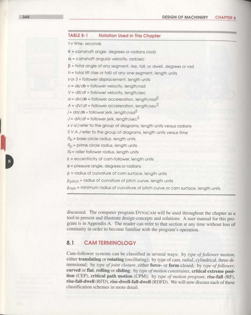
346 DESIGN OF MACHINERY CHAPTER 8 TABLE 8-1 Notation Used in This Chapter t=time,seconds 0=camshaft angle,degrees or radians(rad) camshaft angular velocity,rad/sec B=total angle of any segment,rise.fall,or dwell.degrees or rad h=total llft (rise or fall)of any one segment.length units s or S=follower displacement,length units v=ds/de follower velocity.length/rad V=ds/dt=follower velocity,length/sec a=dv/de=follower acceleration,length/rad2 A=dV/dt=follower acceleration.length/sec2 /=da/de=follower jerk.length/rad3 J=dA/dt=follower jerk,length/sec3 s v ajrefer to the group of diagrams,length units versus radians S V A Jrefer to the group of diagrams,length units versus time Ro=base circle radius,length units Ro=prime circle radius.length units R,=roller follower radius.length units e=eccentricity of cam-follower.length units o=pressure angle.degrees or radians p radius of curvature of cam surface.length units Ppitch=radius of curvature of pitch curve,length units Pmin=minimum radius of curvature of pitch curve or cam surface,length units discussed.The computer program DYNACAM will be used throughout the chapter as a tool to present and illustrate design concepts and solutions.A user manual for this pro- gram is in Appendix A.The reader can refer to that section at any time without loss of continuity in order to become familiar with the program's operation. 8.1 CAM TERMINOLOGY Cam-follower systems can be classified in several ways:by type of follower motion, either translating or rotating (oscillating):by type of cam,radial,cylindrical,three-di- mensional;by rype of joint closure,either force-or form-closed;by type of follower. curved or flat,rolling or sliding:by rype of motion constraints,eritical extreme posi- tion(CEP).critical path motion(CPM):by rype of motion program,rise-fall(RF), rise-fall-dwell(RFD).rise-dwell-fall-dwell(RDFD).We will now discuss each of these classification schemes in more detail
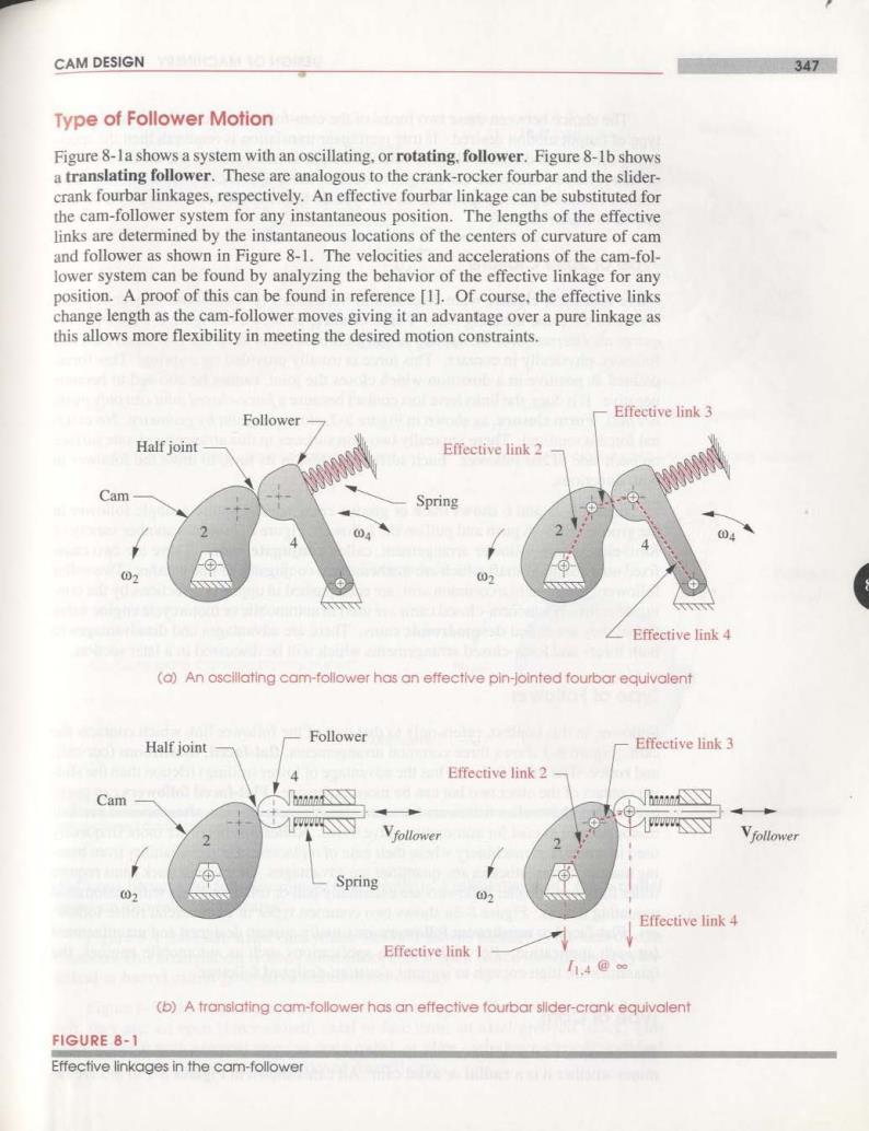
CAM DESIGN 347 Type of Follower Motion Figure 8-la shows a system with an oscillating.or rotating.follower.Figure 8-1b shows a translating follower.These are analogous to the crank-rocker fourbar and the slider- crank fourbar linkages,respectively.An effective fourbar linkage can be substituted for the cam-follower system for any instantaneous position.The lengths of the effective links are determined by the instantaneous locations of the centers of curvature of cam and follower as shown in Figure 8-1.The velocities and accelerations of the cam-fol- lower system can be found by analyzing the behavior of the effective linkage for any position.A proof of this can be found in reference [1].Of course,the effective links change length as the cam-follower moves giving it an advantage over a pure linkage as this allows more flexibility in meeting the desired motion constraints. Follower Effeetive link 3 Half joint Effective link 2 Cam Spring 2 04 02 02 Effective link 4 (a)An oscillating cam-follower has an effective pin-jointed fourbar equivalent Follower Half joint Effective link 3 Effective link 2 Cam Vfollower Vfollower Spring ④ 02 02 Effective link 4 Effective link I h.4@∞ (b)A translating cam-follower has an effective fourbar sllder-crank equivalent FIGURE 8-1 Effective linkages in the cam-follower
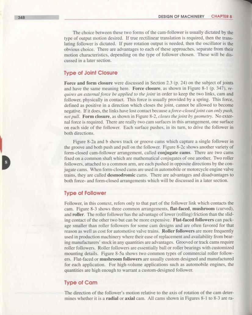
348 DESIGN OF MACHINERY CHAPTER 8 The choice between these two forms of the cam-follower is usually dictated by the type of output motion desired.If true rectilinear translation is required,then the trans- lating follower is dictated.If pure rotation output is needed,then the oscillator is the obvious choice.There are advantages to each of these approaches,separate from their motion characteristics,depending on the type of follower chosen.These will be dis- cussed in a later section. Type of Joint Closure Force and form closure were discussed in Section 2.3(p.24)on the subject of joints and have the same meaning here.Force closure,as shown in Figure 8-1(p.347),re. quires an external force be applied to the joint in order to keep the two links,cam and follower,physically in contact.This force is usually provided by a spring.This force. defined as positive in a direction which closes the joint,cannot be allowed to become negative.If it does,the links have lost contact because a force-closed joint can only push. not pull.Form closure,as shown in Figure 8-2,closes the joint by geometry.No exter- nal force is required.There are really two cam surfaces in this arrangement,one surface on each side of the follower.Each surface pushes,in its turn.to drive the follower in both directions. Figure 8-2a and b shows track or groove cams which capture a single follower in the groove and both push and pull on the follower.Figure 8-2c shows another variety of form-closed cam-follower arrangement,called conjugate cams.There are two cams fixed on a common shaft which are mathematical conjugates of one another.Two roller followers,attached to a common arm,are each pushed in opposite directions by the con- jugate cams.When form-closed cams are used in automobile or motorcycle engine valve trains,they are called desmodromic cams.There are advantages and disadvantages to both force-and form-closed arrangements which will be discussed in a later section. Type of Follower Follower,in this context,refers only to that part of the follower link which contacts the cam.Figure 8-3 shows three common arrangements,flat-faced,mushroom(curved). and roller.The roller follower has the advantage of lower(rolling)friction than the slid- ing contact of the other two but can be more expensive.Flat-faced followers can pack- age smaller than roller followers for some cam designs and are often favored for that reason as well as cost for automotive valve trains.Roller followers are more frequently used in production machinery where their ease of replacement and availability from bear- ing manufacturers'stock in any quantities are advantages.Grooved or track cams require roller followers.Roller followers are essentially ball or roller bearings with customized mounting details.Figure 8-5a shows two common types of commercial roller follow- ers.Flat-faced or mushroom followers are usually custom designed and manufactured for each application.For high-volume applications such as automobile engines,the quantities are high enough to warrant a custom-designed follower. Type of Cam The direction of the follower's motion relative to the axis of rotation of the cam deter- mines whether it is a radial or axial cam.All cams shown in Figures 8-1 to 8-3 are ra-
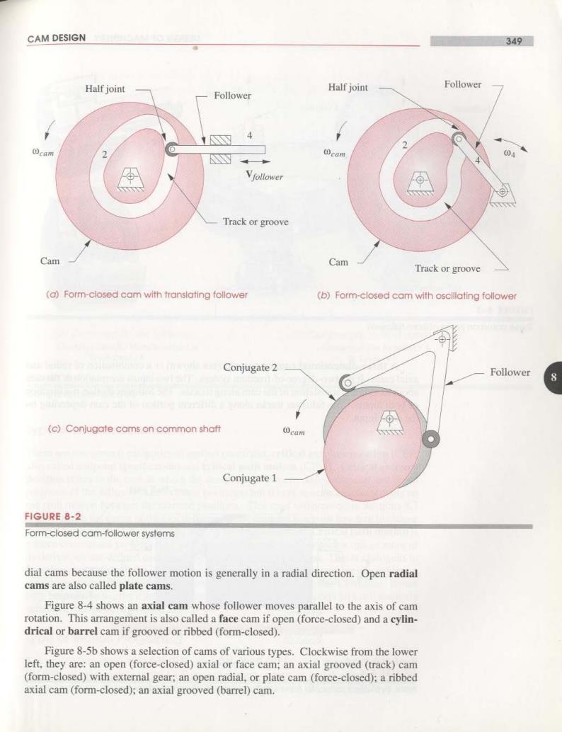
CAM DESIGN 349 Half joint Half joint Follower Follower I cam 2 Y cam 04 Vfollower Track or groove Cam Cam Track or groove (a)Form-closed cam with translating follower (b)Form-closed cam with oscillating follower Conjugate 2 Follower 8 (c)Conjugate cams on common shaft cam Conjugate 1 FIGURE 8-2 Form-closed cam-follower systems dial cams because the follower motion is generally in a radial direction.Open radial cams are also called plate cams. Figure 8-4 shows an axial cam whose follower moves parallel to the axis of cam rotation.This arrangement is also called a face cam if open(force-closed)and a cylin- drical or barrel cam if grooved or ribbed(form-closed). Figure 8-5b shows a selection of cams of various types.Clockwise from the lower left,they are:an open (force-closed)axial or face cam;an axial grooved (track)cam (form-closed)with external gear;an open radial,or plate cam(force-closed):a ribbed axial cam(form-closed);an axial grooved (barrel)cam