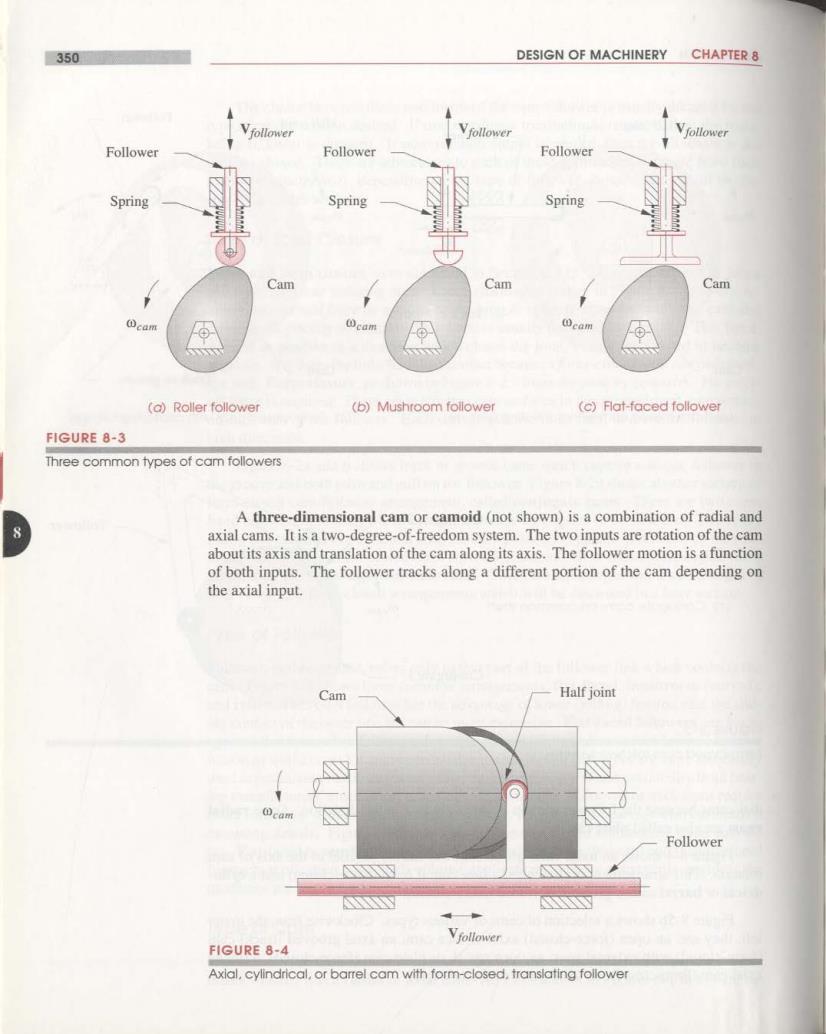
350 DESIGN OF MACHINERY CHAPTER 8 Vfollower Vfollower Vfollower Follower Follower Follower Spring Spring Spring Cam Cam Cam ①cae cam cam (a)Roller follower (b)Mushroom follower (c)Flat-faced follower FIGURE 8-3 Three common types of cam followers A three-dimensional cam or camoid(not shown)is a combination of radial and 8 axial cams.It is a two-degree-of-freedom system.The two inputs are rotation of the cam about its axis and translation of the cam along its axis.The follower motion is a function of both inputs.The follower tracks along a different portion of the cam depending on the axial input. Cam Half joint Follower N Vfollower FIGURE 8-4 Axial,cylindrical,or barrel cam with form-closed,translating follower
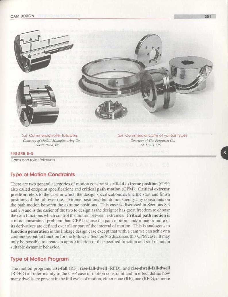
CAM DESIGN 351m (o)Commercial roller followers (b)Commercial cams of varlous types Courtesy of MeGill Manufacturing Co. Courtesy of The Ferguson Co. South Bend.IN St.Louis,MS FIGURE 8-5 8 Cams and roller followers Type of Motion Constraints There are two general categories of motion constraint,critical extreme position(CEP: also called endpoint specification)and critical path motion(CPM).Critical extreme position refers to the case in which the design specifications define the start and finish positions of the follower (i.e.,extreme positions)but do not specify any constraints on the path motion between the extreme positions.This case is discussed in Sections 8.3 and 8.4 and is the easier of the two to design as the designer has great freedom to choose the cam functions which control the motion between extremes.Critical path motion is a more constrained problem than CEP because the path motion.and/or one or more of its derivatives are defined over all or part of the interval of motion.This is analogous to function generation in the linkage design case except that with a cam we can achieve a continuous output function for the follower.Section 8.6 discusses this CPM case.It may only be possible to create an approximation of the specified function and still maintain suitable dynamic behavior. Type of Motion Program The motion programs rise-fall(RF),rise-fall-dwell(RFD),and rise-dwell-fall-dwell (RDFD)all refer mainly to the CEP case of motion constraint and in effect define how many dwells are present in the full cycle of motion.either none(RF),one(RFD),or more
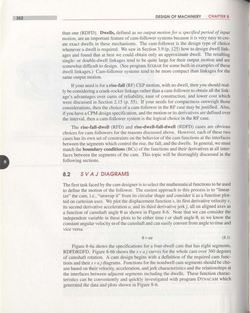
352 DESIGN OF MACHINERY CHAPTER 8 than one (RDFD).Dwells,defined as no output motion for a specified period of input motion,are an important feature of cam-follower systems because it is very easy to cre- ate exact dwells in these mechanisms.The cam-follower is the design type of choice whenever a dwell is required.We saw in Section 3.9(p.125)how to design dwell link- ages and found that at best we could obtain only an approximate dwell.The resulting single-or double-dwell linkages tend to be quite large for their output motion and are somewhat difficult to design.(See program SIXBAR for some built-in examples of these dwell linkages.)Cam-follower systems tend to be more compact than linkages for the same output motion. If your need is for a rise-fall(RF)CEP motion,with no dwell,then you should real- ly be considering a crank-rocker linkage rather than a cam-follower to obtain all the link- age's advantages over cams of reliability.ease of construction,and lower cost which were discussed in Section 2.15(p.55).If your needs for compactness outweigh those considerations,then the choice of a cam-follower in the RF case may be justified.Also, if you have a CPM design specification,and the motion or its derivatives are defined over the interval,then a cam-follower system is the logical choice in the RF case. The rise-fall-dwell(RFD)and rise-dwell-fall-dwell(RDFD)cases are obvious choices for cam-followers for the reasons discussed above.However,each of these two cases has its own set of constraints on the behavior of the cam functions at the interfaces between the segments which control the rise,the fall,and the dwells.In general,we must match the boundary conditions(BCs)of the functions and their derivatives at all inter- faces between the segments of the cam.This topic will be thoroughly discussed in the following sections. 8.2 SVAJ DIAGRAMS The first task faced by the cam designer is to select the mathematical functions to be used to define the motion of the follower.The easiest approach to this process is to"linear- ize"the cam,i.e.,"unwrap it"from its circular shape and consider it as a function plot- ted on cartesian axes.We plot the displacement function s,its first derivative velocity v. its second derivative acceleration a,and its third derivative jerk j,all on aligned axes as a function of camshaft angle 0 as shown in Figure 8-6.Note that we can consider the independent variable in these plots to be either time t or shaft angle 0,as we know the constant angular velocity c of the camshaft and can easily convert from angle to time and vice versa. 6=0t (8.0 Figure 8-6a shows the specifications for a four-dwell cam that has eight segments, RDFDRDFD.Figure 8-6b shows the svajcurves for the whole cam over 360 degrees of camshaft rotation.A cam design begins with a definition of the required cam func- tions and their s va jdiagrams.Functions for the nondwell cam segments should be cho- sen based on their velocity,acceleration,and jerk characteristics and the relationships at the interfaces between adjacent segments including the dwells.These function charac- teristics can be conveniently and quickly investigated with program DYNACAM which generated the data and plots shown in Figure 8-6
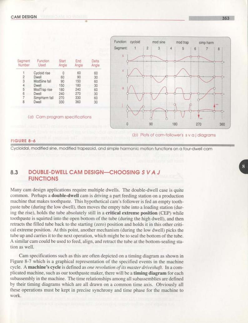
CAM DESIGN 353■ Function:cycloid mod sine mod trap simp harm Segment: 1 2 3 4 5 6 个 8 Segment Function Start End Delta Number Used Angle Angle Angle Cycloid rise 0 Dwell 90 ModSine fall 90 1 60 Dwell 150 180 ModTrap rise 180 240 6 Dwell 240 270 SimpHarm fall 270 330 0509050 8 Dwell 330 360 0 (a)Cam program specifications 180 270 360 (b)Plots of cam-follower's s v aj diagrams FIGURE 8-6 Cycloldal,modified sine,modified trapezoid,and simple harmonic motion functions on a four-dwell cam 8 8.3 DOUBLE-DWELL CAM DESIGN-CHOOSING S VAJ FUNCTIONS Many cam design applications require multiple dwells.The double-dwell case is quite common.Perhaps a double-dwell cam is driving a part feeding station on a production machine that makes toothpaste.This hypothetical cam's follower is fed an empty tooth- paste tube(during the low dwell),then moves the empty tube into a loading station(dur- ing the rise),holds the tube absolutely still in a critical extreme position(CEP)while toothpaste is squirted into the open bottom of the tube(during the high dwell),and then retracts the filled tube back to the starting(zero)position and holds it in this other criti- cal extreme position.At this point,another mechanism(during the low dwell)picks the tube up and carries it to the next operation,which might be to seal the bottom of the tube. A similar cam could be used to feed,align,and retract the tube at the bottom-sealing sta- tion as well. Cam specifications such as this are often depicted on a timing diagram as shown in Figure 8-7 which is a graphical representation of the specified events in the machine cycle.A machine's cycle is defined as one revolution of its master driveshaft.In a com- plicated machine,such as our toothpaste maker,there will be a timing diagram for each subassembly in the machine.The time relationships among all subassemblies are defined by their timing diagrams which are all drawn on a common time axis.Obviously all these operations must be kept in precise synchrony and time phase for the machine to work
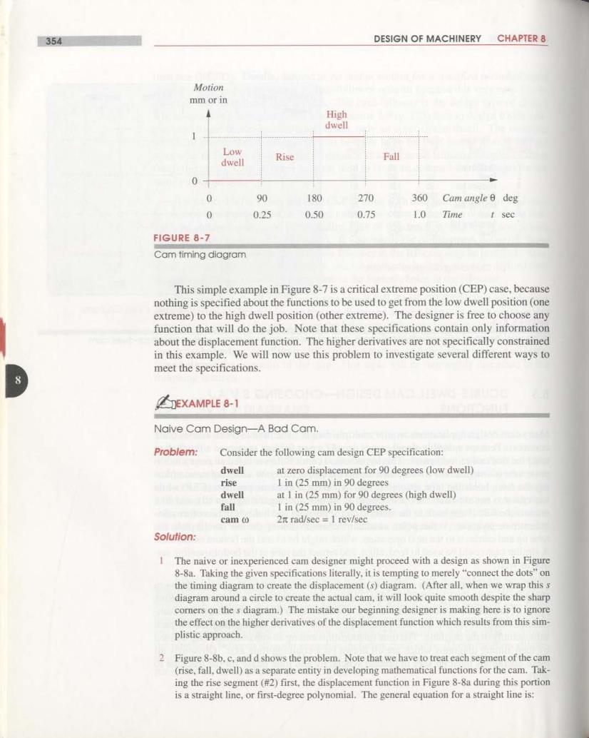
354 DESIGN OF MACHINERY CHAPTER 8 Motion mm or in High dwell Low dwell Rise Fall 0 0 90 180 270 360 Cam angle B deg 0 0.25 0.50 0.75 1.0 Time t sec FIGURE 8-7 Cam timing diagram This simple example in Figure 8-7 is a critical extreme position(CEP)case,because nothing is specified about the functions to be used to get from the low dwell position (one extreme)to the high dwell position(other extreme).The designer is free to choose any function that will do the job.Note that these specifications contain only information about the displacement function.The higher derivatives are not specifically constrained in this example.We will now use this problem to investigate several different ways to meet the specifications. EXAMPLE 8-1 Naive Cam Design-A Bad Cam. Problem: Consider the following cam design CEP specification: dwell at zero displacement for 90 degrees (low dwell) rise 1 in(25 mm)in 90 degrees dwell at 1 in(25 mm)for 90 degrees (high dwell) fall I in (25 mm)in 90 degrees. cam o 2n rad/sec 1 rev/sec Solution: 1 The naive or inexperienced cam designer might proceed with a design as shown in Figure 8-8a.Taking the given specifications literally,it is tempting to merely "connect the dots"on the timing diagram to create the displacement(s)diagram.(After all,when we wrap this s diagram around a circle to create the actual cam,it will look quite smooth despite the sharp comners on the s diagram.)The mistake our beginning designer is making here is to ignore the effect on the higher derivatives of the displacement function which results from this sim- plistic approach. 2 Figure 8-8b.c,and d shows the problem.Note that we have to treat each segment of the cam (rise,fall.dwell)as a separate entity in developing mathematical functions for the cam.Tak- ing the rise segment(#2)first,the displacement function in Figure 8-8a during this portion is a straight line,or first-degree polynomial.The general equation for a straight line is: