
Chapter GEAR TRAINS Cycle and epicycle, orb in orb JOHN MILTON.PARADISE LOST 9 9.0 INTRODUCTION The earliest known reference to gear trains is in a treatise by Hero of Alexandria(c.100 B.C.).Gear trains are widely used in all kinds of mechanisms and machines,from can openers to aircraft carriers.Whenever a change in the speed or torque of a rotating de- vice is needed,a gear train or one of its cousins.the belt or chain drive mechanism,will usually be used.This chapter will explore the theory of gear tooth action and the design of these ubiquitous devices for motion control.The calculations involved are trivial compared to those for cams or linkages.The shape of gear teeth has become quite stan- dardized for good kinematic reasons which we will explore. Gears of various sizes and styles are readily available from many manufacturers. Assembled gearboxes for particular ratios are also stock items.The kinematic design of gear trains is principally involved with the selection of appropriate ratios and gear diam- eters.A complete gear train design will necessarily involve considerations of strength of materials and the complicated stress states to which gear teeth are subjected.This text will not deal with the stress analysis aspects of gear design.There are many texts which do.Some are listed in the bibliography at the end of this chapter.This chapter will dis- cuss the kinematics of gear tooth theory,gear types,and the kinematic design of gearsets and gear trains of simple,compound,reverted,and epicyclic types.Chain and belt drives will also be discussed.Examples of the use of these devices will be presented as well. 432
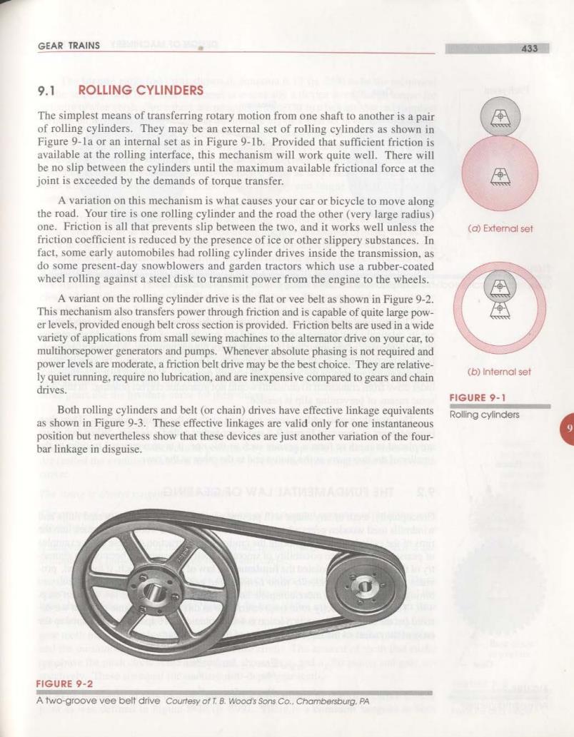
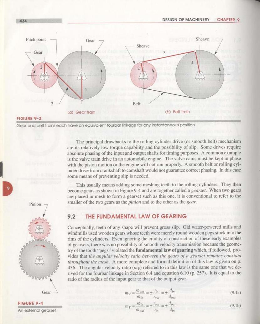
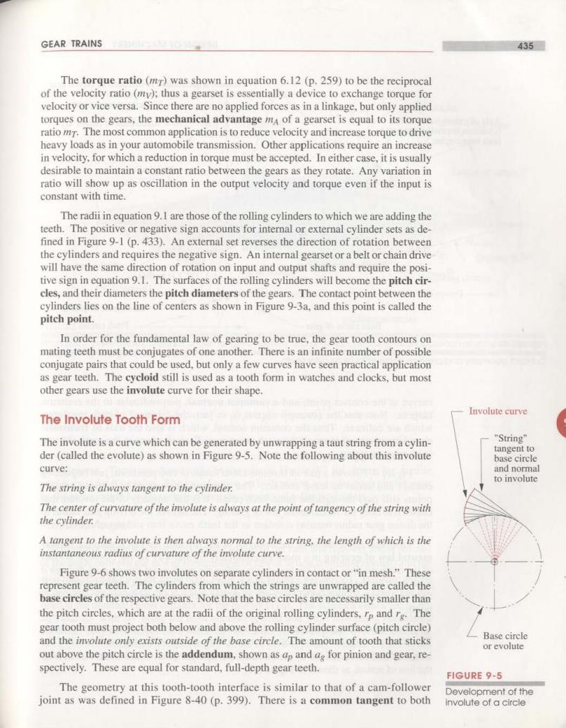
GEAR TRAINS 433 9.1 ROLLING CYLINDERS The simplest means of transferring rotary motion from one shaft to another is a pair of rolling cylinders.They may be an external set of rolling cylinders as shown in Figure 9-1a or an internal set as in Figure 9-1b.Provided that sufficient friction is available at the rolling interface,this mechanism will work quite well.There will be no slip between the cylinders until the maximum available frictional force at the joint is exceeded by the demands of torque transfer. A variation on this mechanism is what causes your car or bicycle to move along the road.Your tire is one rolling cylinder and the road the other(very large radius) one.Friction is all that prevents slip between the two,and it works well unless the (a)Extemal set friction coefficient is reduced by the presence of ice or other slippery substances.In fact,some early automobiles had rolling cylinder drives inside the transmission.as do some present-day snowblowers and garden tractors which use a rubber-coated wheel rolling against a steel disk to transmit power from the engine to the wheels. A variant on the rolling cylinder drive is the flat or vee belt as shown in Figure 9-2. This mechanism also transfers power through friction and is capable of quite large pow- er levels,provided enough belt cross section is provided.Friction belts are used in a wide variety of applications from small sewing machines to the alternator drive on your car,to multihorsepower generators and pumps.Whenever absolute phasing is not required and power levels are moderate,a friction belt drive may be the best choice.They are relative- ly quiet running,require no lubrication,and are inexpensive compared to gears and chain (b)Intemnal set drives. FIGURE 9-1 Both rolling cylinders and belt(or chain)drives have effective linkage equivalents Rolling cylinders as shown in Figure 9-3.These effective linkages are valid only for one instantaneous position but nevertheless show that these devices are just another variation of the four- bar linkage in disguise. FIGURE 9-2 A two-groove vee belt drive Courtesy of T.B.Wood's Sons Co..Chambersburg.PA
434 DESIGN OF MACHINERY CHAPTER 9 Pitch point Gear Sheave Sheave Gear 3 Belt (a)Gear train (b)Belt train FIGURE 9-3 Gear and belt trains each have an equivalent fourbar linkage for any Instantaneous position The principal drawbacks to the rolling cylinder drive (or smooth belt)mechanism are its relatively low torque capability and the possibility of slip.Some drives require absolute phasing of the input and output shafts for timing purposes.A common example is the valve train drive in an automobile engine.The valve cams must be kept in phase with the piston motion or the engine will not run properly.A smooth belt or rolling cyl- inder drive from crankshaft to camshaft would not guarantee correct phasing.In this case some means of preventing slip is needed. This usually means adding some meshing teeth to the rolling cylinders.They then become gears as shown in Figure 9-4 and are together called a gearset.When two gears are placed in mesh to form a gearset such as this one,it is conventional to refer to the Pinion smaller of the two gears as the pinion and to the other as the gear. 9.2 THE FUNDAMENTAL LAW OF GEARING Conceptually,teeth of any shape will prevent gross slip.Old water-powered mills and windmills used wooden gears whose teeth were merely round wooden pegs stuck into the rims of the cylinders.Even ignoring the crudity of construction of these early examples of gearsets.there was no possibility of smooth velocity transmission because the geome- try of the tooth"pegs"violated the fundamental law of gearing which,if followed,pro- vides that the angular velocity ratio between the gears of a gearset remains constant throughout the mesh.A more complete and formal definition of this law is given on p. 436.The angular velocity ratio (my)referred to in this law is the same one that we de- rived for the fourbar linkage in Section 6.4 and equation 6.10(p.257).It is equal to the ratio of the radius of the input gear to that of the output gear. Gear mv=oau=±n=土dm (9.1a) in dowt FIGURE 9-4 功T= 0n=tot=士 out (9.1b) An external gearset out m din
GEAR TRAINS 435 The torque ratio(m)was shown in equation 6.12(p.259)to be the reciprocal of the velocity ratio (my):thus a gearset is essentially a device to exchange torque for velocity or vice versa.Since there are no applied forces as in a linkage,but only applied torques on the gears,the mechanical advantage mA of a gearset is equal to its torque ratio m.The most common application is to reduce velocity and increase torque to drive heavy loads as in your automobile transmission.Other applications require an increase in velocity,for which a reduction in torque must be accepted.In either case,it is usually desirable to maintain a constant ratio between the gears as they rotate.Any variation in ratio will show up as oscillation in the output velocity and torque even if the input is constant with time. The radii in equation 9.I are those of the rolling cylinders to which we are adding the teeth.The positive or negative sign accounts for internal or external cylinder sets as de- fined in Figure 9-1(p.433).An external set reverses the direction of rotation between the cylinders and requires the negative sign.An internal gearset or a belt or chain drive will have the same direction of rotation on input and output shafts and require the posi- tive sign in equation 9.1.The surfaces of the rolling cylinders will become the pitch cir- cles,and their diameters the pitch diameters of the gears.The contact point between the cylinders lies on the line of centers as shown in Figure 9-3a,and this point is called the pitch point. In order for the fundamental law of gearing to be true,the gear tooth contours on mating teeth must be conjugates of one another.There is an infinite number of possible conjugate pairs that could be used,but only a few curves have seen practical application as gear teeth.The cycloid still is used as a tooth form in watches and clocks.but most other gears use the involute curve for their shape. Involute curve The Involute Tooth Form The involute is a curve which can be generated by unwrapping a taut string from a cylin- "String”" tangent to der(called the evolute)as shown in Figure 9-5.Note the following about this involute base circle curve: and normal to involute The string is always tangent to the cylinder. The center of curvature of the involute is always at the point of tangency of the string with the cylinder. A tangent to the involute is then always normal to the string,the length of which is the instantaneous radius of curvature of the involute curve. Figure 9-6 shows two involutes on separate cylinders in contact or"in mesh."These represent gear teeth.The cylinders from which the strings are unwrapped are called the base cireles of the respective gears.Note that the base circles are necessarily smaller than the pitch circles,which are at the radii of the original rolling cylinders,rp and rg.The gear tooth must project both below and above the rolling cylinder surface(pitch circle) and the involute only exists outside of the base circle.The amount of tooth that sticks Base circle or evolute out above the pitch circle is the addendum,shown as ap and ag for pinion and gear,re- spectively.These are equal for standard,full-depth gear teeth. FIGURE 9-5 The geometry at this tooth-tooth interface is similar to that of a cam-follower Development of the joint as was defined in Figure 8-40(p.399).There is a common tangent to both involute of a circle
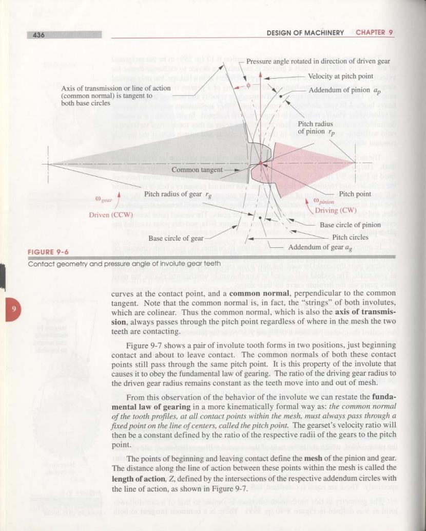
436 DESIGN OF MACHINERY CHAPTER 9 Pressure angle rotated in direction of driven gear Velocity at pitch point Axis of transmission or line of action Addendum of pinion ap (common normal)is tangent to both base circles Pitch radius of pinion rp Common tangent geur Pitch radius of gear re Pitch point pinion Driven(CCW) Driving(CW) Base circle of pinion Base circle of gear Pitch circles FIGURE 9-6 Addendum of gear ag Contact geometry and pressure angle of involute gear teeth curves at the contact point,and a common normal,perpendicular to the common tangent.Note that the common normal is,in fact,the "strings"of both involutes, which are colinear.Thus the common normal,which is also the axis of transmis- sion,always passes through the pitch point regardless of where in the mesh the two teeth are contacting. Figure 9-7 shows a pair of involute tooth forms in two positions,just beginning contact and about to leave contact.The common normals of both these contact points still pass through the same pitch point.It is this property of the involute that causes it to obey the fundamental law of gearing.The ratio of the driving gear radius to the driven gear radius remains constant as the teeth move into and out of mesh. From this observation of the behavior of the involute we can restate the funda- mental law of gearing in a more kinematically formal way as:the common normal of the tooth profiles,at all contact points within the mesh,must always pass through a fixed point on the line of centers,called the pitch point.The gearset's velocity ratio will then be a constant defined by the ratio of the respective radii of the gears to the pitch point. The points of beginning and leaving contact define the mesh of the pinion and gear. The distance along the line of action between these points within the mesh is called the length of action,Z,defined by the intersections of the respective addendum circles with the line of action,as shown in Figure 9-7