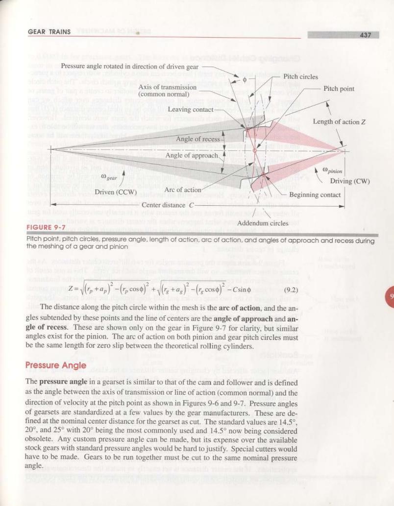
GEAR TRAINS 437 Pressure angle rotated in direction of driven gear Pitch circles Axis of transmission Pitch point (common normal) Leaving contact Length of action Z Angle of recess Angle of approach. gear pinion Driving(CW) Driven(CCW) Arc of action Beginning contact Center distance C- FIGURE 9-7 Addendum circles Pitch point,pitch circles,pressure angle,length of action.arc of action.and angles of approach and recess during the meshing of a gear and pinion z-p+ap)-(c)++a)-(cos)-csino (92) The distance along the pitch circle within the mesh is the are of action,and the an- gles subtended by these points and the line of centers are the angle of approach and an- gle of recess.These are shown only on the gear in Figure 9-7 for clarity,but similar angles exist for the pinion.The arc of action on both pinion and gear pitch circles must be the same length for zero slip between the theoretical rolling cylinders. Pressure Angle The pressure angle in a gearset is similar to that of the cam and follower and is defined as the angle between the axis of transmission or line of action(common normal)and the direction of velocity at the pitch point as shown in Figures 9-6 and 9-7.Pressure angles of gearsets are standardized at a few values by the gear manufacturers.These are de- fined at the nominal center distance for the gearset as cut.The standard values are 14.5, 20°,and25°with20°being the most commonly used and 14.5°now being considered obsolete.Any custom pressure angle can be made,but its expense over the available stock gears with standard pressure angles would be hard to justify.Special cutters would have to be made.Gears to be run together must be cut to the same nominal pressure angle
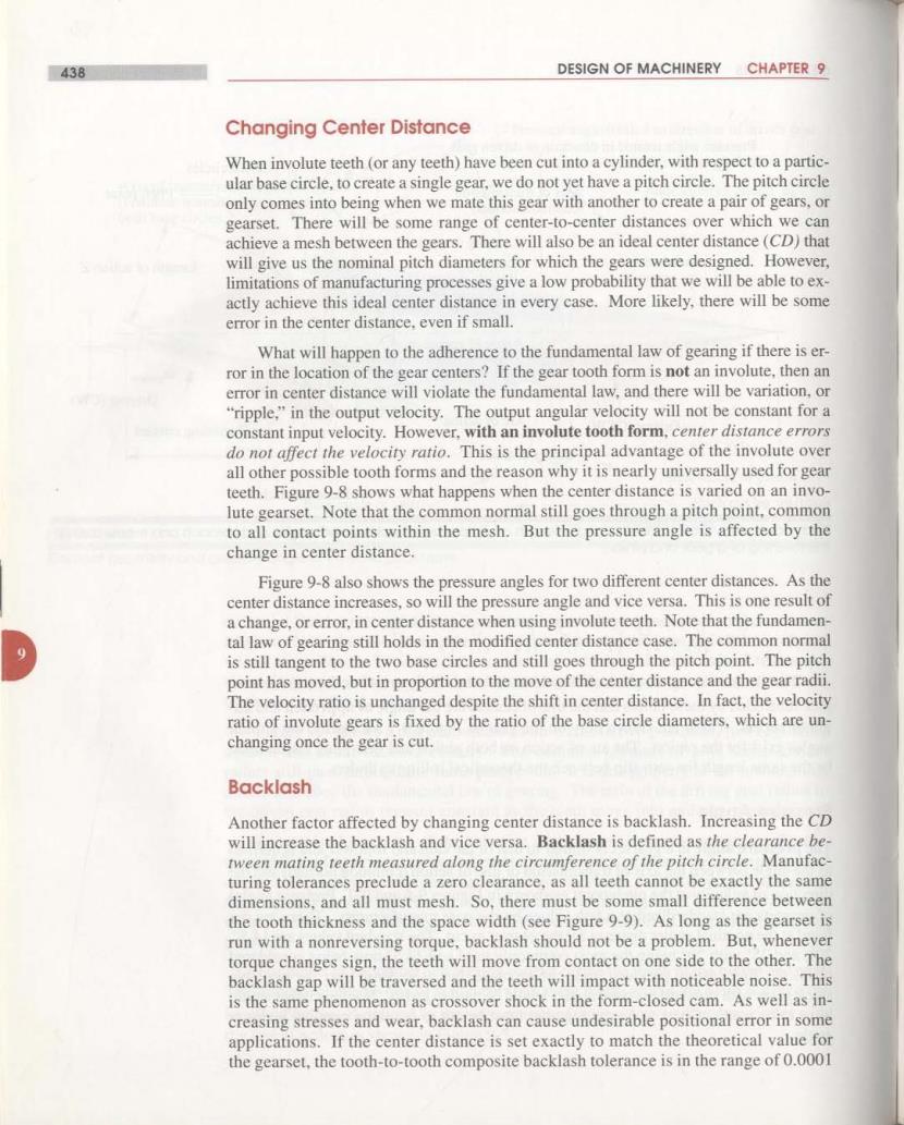
438 DESIGN OF MACHINERY CHAPTER 9 Changing Center Distance When involute teeth(or any teeth)have been cut into a cylinder,with respect to a partic- ular base circle,to create a single gear,we do not yet have a pitch circle.The pitch circle only comes into being when we mate this gear with another to create a pair of gears,or gearset.There will be some range of center-to-center distances over which we can achieve a mesh between the gears.There will also be an ideal center distance(CD)that will give us the nominal pitch diameters for which the gears were designed.However, limitations of manufacturing processes give a low probability that we will be able to ex- actly achieve this ideal center distance in every case.More likely,there will be some error in the center distance,even if small. What will happen to the adherence to the fundamental law of gearing if there is er- ror in the location of the gear centers?If the gear tooth form is not an involute,then an error in center distance will violate the fundamental law,and there will be variation,or "ripple,"in the output velocity.The output angular velocity will not be constant for a constant input velocity.However,with an involute tooth form,center distance errors do not affect the velocity ratio.This is the principal advantage of the involute over all other possible tooth forms and the reason why it is nearly universally used for gear teeth.Figure 9-8 shows what happens when the center distance is varied on an invo- lute gearset.Note that the common normal still goes through a pitch point,common to all contact points within the mesh.But the pressure angle is affected by the change in center distance. Figure 9-8 also shows the pressure angles for two different center distances.As the center distance increases,so will the pressure angle and vice versa.This is one result of a change,or error,in center distance when using involute teeth.Note that the fundamen- tal law of gearing still holds in the modified center distance case.The common normal is still tangent to the two base circles and still goes through the pitch point.The pitch point has moved,but in proportion to the move of the center distance and the gear radii The velocity ratio is unchanged despite the shift in center distance.In fact,the velocity ratio of involute gears is fixed by the ratio of the base circle diameters,which are un- changing once the gear is cut. Backlash Another factor affected by changing center distance is backlash.Increasing the CD will increase the backlash and vice versa.Backlash is defined as the clearance be- tween mating teeth measured along the circumference of the pitch circle.Manufac- turing tolerances preclude a zero clearance,as all teeth cannot be exactly the same dimensions,and all must mesh.So,there must be some small difference between the tooth thickness and the space width(see Figure 9-9).As long as the gearset is run with a nonreversing torque,backlash should not be a problem.But,whenever torque changes sign,the teeth will move from contact on one side to the other.The backlash gap will be traversed and the teeth will impact with noticeable noise.This is the same phenomenon as crossover shock in the form-closed cam.As well as in- creasing stresses and wear,backlash can cause undesirable positional error in some applications.If the center distance is set exactly to match the theoretical value for the gearset,the tooth-to-tooth composite backlash tolerance is in the range of 0.0001
GEAR TRAINS 439 to 0.0007 in for precision gears.The increase in angular backlash as a function of error in center distance is approximately 6B=43200(4Can minutes of arc (9.3) where pressure angle,AC error in center distance,and d pitch diameter of the gear on the shaft where the backlash is measured. In servomechanisms,where motors are driving,for example,the control surfac- es on an aircraft,backlash can cause potentially destructive "hunting"in which the control system tries in vain to correct positional errors due to backlash"slop"in the mechanical drive system.Such applications need antibacklash gears which are really two gears back-to-back on the same shaft which can be rotated slightly at as- sembly with respect to one another,and then fixed so as to take up the backlash.In less critical applications,such as the propeller drive on a boat,backlash on reversal will not even be noticed. Shift in center distance New pitch point Pitch New,larger Base circle pitch radius radius of is unchanged pinion Pitch point of pinion shifts position Velocity at New pitch 9 pitch point circles Base circle is unchanged Pressure New angle Pitch pressure radius angle New,larger 0=20° of gear 0=23° pitch radius of gear Line of action (common normal) is tangent to both base circles (o)Correct center distance (b)Increased center distance FIGURE 9-8 Changing center distance of involute gears changes the pressure angle and pitch diameters
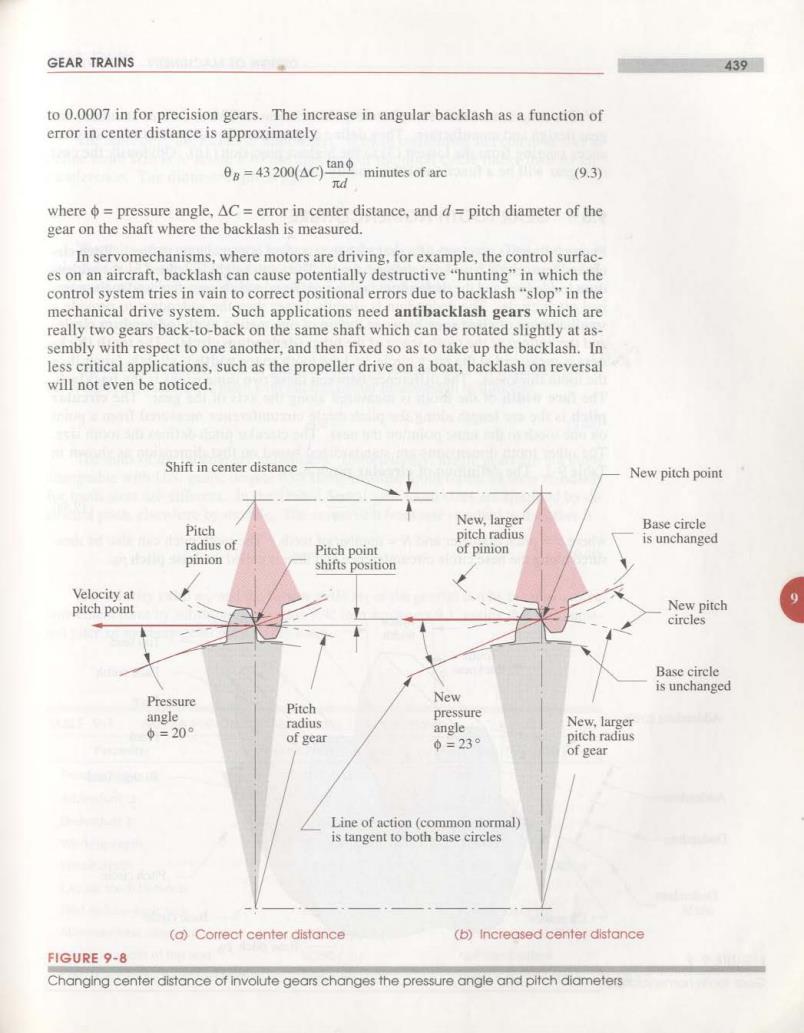
440 DESIGN OF MACHINERY CHAPTER 9 The American Gear Manufacturers Association (AGMA)defines standards for gear design and manufacture.They define a spectrum of quality numbers and toler- ances ranging from the lowest(3)to the highest precision (16).Obviously the cost of a gear will be a function of this quality index. 9.3 GEAR TOOTH NOMENCLATURE Figure 9-9 shows two teeth of a gear with the standard nomenclature defined.Pitch cir- cle and base circle have been defined above.The tooth height is defined by the adden- dum (added on)and the dedendum (subtracted from)which are referenced to the nom- inal pitch circle.The dedendum is slightly larger than the addendum to provide a small amount of clearance between the tip of one mating tooth(addendum circle) and the bottom of the tooth space of the other(dedendum circle).The tooth thick- ness is measured at the pitch circle,and the tooth space width is slightly larger than the tooth thickness.The difference between these two dimensions is the backlash. The face width of the tooth is measured along the axis of the gear.The circular pitch is the arc length along the pitch circle circumference measured from a point on one tooth to the same point on the next.The circular pitch defines the tooth size. The other tooth dimensions are standardized based on that dimension as shown in Table 9-1.The definition of circular pitch pe is: 么s N (9.4a) where d=pitch diameter and N=number of teeth.The tooth pitch can also be mea- sured along the base circle circumference and then is called the base pitch po. Space Circular pitch Pe width Top land Tooth thickness Face width Face Addendum circle Flank Bottom land Addendum Dedendum Pitch circle Dedendum circle Clearance Base circle Base pitch ph FIGURE 9-9 Gear tooth nomenclature
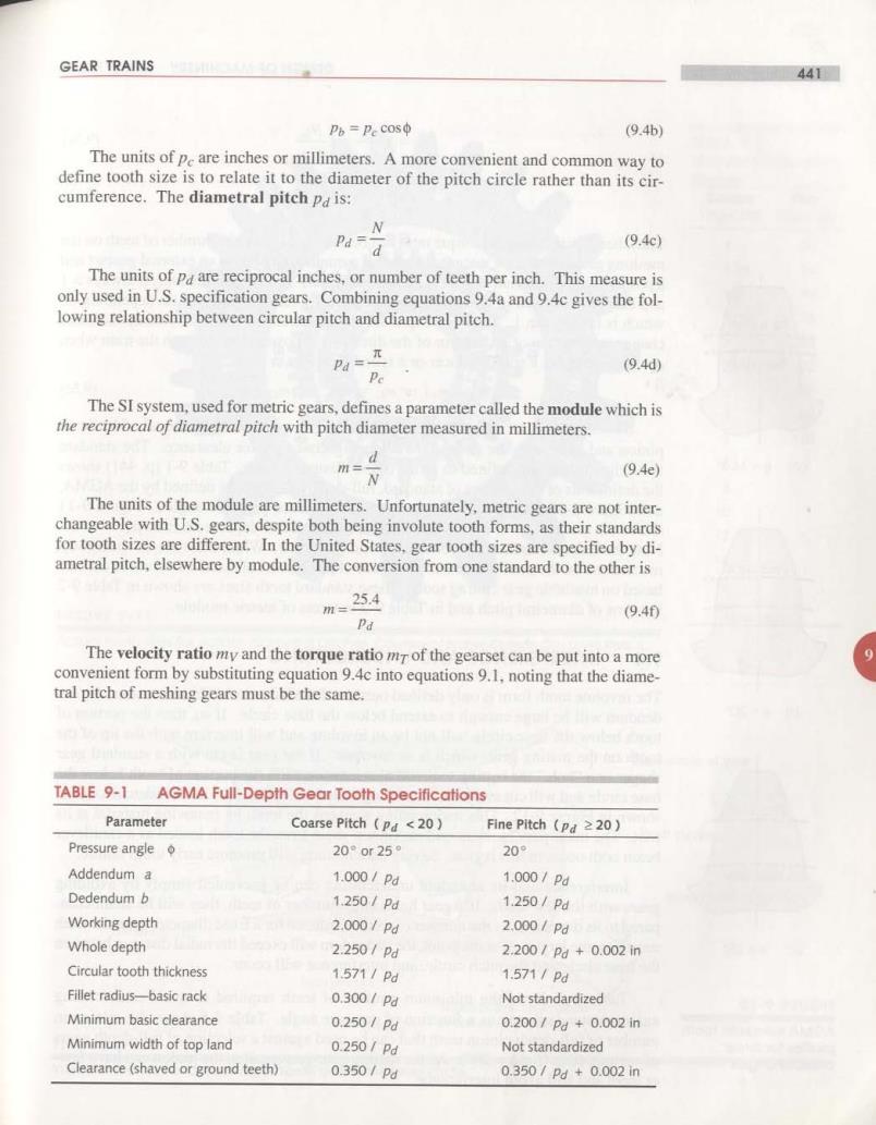
GEAR TRAINS 441 Pb=pe cosφ (9.4b) The units of pe are inches or millimeters.A more convenient and common way to define tooth size is to relate it to the diameter of the pitch circle rather than its cir- cumference.The diametral pitch Pd is: N Pd= d (9.4c) The units of pd are reciprocal inches,or number of teeth per inch.This measure is only used in U.S.specification gears.Combining equations 9.4a and 9.4c gives the fol- lowing relationship between circular pitch and diametral pitch. Pa=n (9.4d) Pe The SI system,used for metric gears,defines a parameter called the module which is the reciprocal of diametral pitch with pitch diameter measured in millimeters. N (9.4e) The units of the module are millimeters.Unfortunately,metric gears are not inter- changeable with U.S.gears,despite both being involute tooth forms,as their standards for tooth sizes are different.In the United States,gear tooth sizes are specified by di- ametral pitch,elsewhere by module.The conversion from one standard to the other is m=254 (9.40 Pa The velocity ratio my and the torque ratio mT of the gearset can be put into a more convenient form by substituting equation 9.4c into equations 9.1,noting that the diame- tral pitch of meshing gears must be the same. TABLE 9-1 AGMA Full-Depth Gear Tooth Specifications Parameter Coarse Pitch (pd <20) Fine Pitch (pd 220) Pressure angle 20°0r25° 20° Addendum a 1.000/Pd 1.000/pd Dedendum b 1.250/Pd 1.250/Pd Working depth 2.000/Pd 2.0o0/Pd Whole depth 2.2501pd 2.200/pd+0.002in Circular tooth thickness 1571/Pd 1.571/Pd Fillet radius-basic rack 0.3001Pd Not standardized Minimum basic clearance 0.250/Pd 0200/Pd+0.002in Minimum width of top land 0.250/Pd Not standardized Clearance(shaved or ground teeth) 0.350/Pd 0.350/pd+0.002n