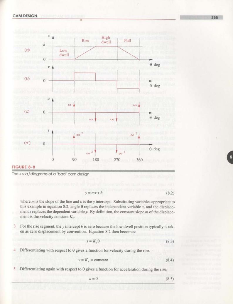
CAM DESIGN 355■ Rise High dwell Fall h (a) Low dwell 0 e deg (b) 0 θdcg (c) 0 deg (d) 0 e deg 0 90 180 270360 FIGURE 8-8 The s vajdlagrams of a'bad'cam design y=mx+b (8.2) where m is the slope of the line and b is the y intercept.Substituting variables appropriate to this example in equation 8.2,angle 0 replaces the independent variable x,and the displace- ment s replaces the dependent variable y.By definition,the constant slope m of the displace- ment is the velocity constant K. 3. For the rise segment,the y intercept b is zero because the low dwell position typically is tak- en as zero displacement by convention.Equation 8.2 then becomes: s=K 0 (8.3) 4 Differentiating with respect to e gives a function for velocity during the rise. =K constant (8.4) 5 Differentiating again with respect to 0 gives a function for acceleration during the rise a=0 (8.5)
356 DESIGN OF MACHINERY CHAPTER 8 This seems too good to be true (and it is).Zero acceleration means zero dynamic force.This cam appears to have no dynamic forces or stresses in it! Figure 8-8 shows what is really happening here.If we return to the displacement function and graphically differentiate it twice,we will observe that,from the definition of the derivative as the instantaneous slope of the function,the acceleration is in fact zero during the interval.But,at the boundaries of the interval,where rise meets low dwell on one side and high dwell on the other,note that the velociry function is multivalued. There are discontinuities at these boundaries.The effect of these discontinuities is to create a portion of the velocity curve which has infinite slope and zero duration.This results in the infinite spikes of acceleration shown at those points. These spikes are more properly called Dirac delta functions.Infinite acceleration cannot really be obtained,as it requires infinite force.Clearly the dynamic forces will be very large at these boundaries and will create high stresses and rapid wear.In fact,if this cam were built and run at any significant speeds,the sharp corners on the displace- ment diagram which are creating these theoretical infinite accelerations would be quick- ly worn to a smoother contour by the unsustainable stresses generated in the materials. This is an unacceptable design. The unacceptability of this design is reinforced by the jerk diagram which shows theoretical values of infinity squared at the discontinuities.The problem has been en- gendered by an inappropriate choice of displacement function.In fact,the cam designer should not be as concerned with the displacement function as with its higher derivatives. 8 The Fundamental Law of Cam Design Any cam designed for operation at other than very low speeds must be designed with the following constraints: The cam function must be continuous through the first and second derivatives of dis- placement across the entire interval (360 degrees). corollary: The jerk function must be finite across the entire interval(360 degrees). In any but the simplest of cams.the cam motion program cannot be defined by a single mathematical expression,but rather must be defined by several separate functions. each of which defines the follower behavior over one segment,or piece,of the cam. These expressions are sometimes called piecewise functions.These functions must have third-order continuity (the function plus two derivatives)at all boundaries.The dis- ◆This rule is stated by placement,velocity and acceleration functions must have no discontinuities in Neklutinl21 but is disputed them." by some other au- thors.3114 Despite the If any discontinuities exist in the acceleration function,then there will be infinite minor controversy over this spikes,or Dirac delta functions,appearing in the derivative of acceleration,jerk.Thus issue,this author believes the corollary merely restates the fundamental law of cam design.Our naive designer that it is a good (and failed to recognize that by starting with a low-degree (linear)polynomial as the displace- simple)rule to follow in ment function,discontinuities would appear in the upper derivatives. order to get acceptable dynamic results with high- Polynomial functions are one of the best choices for cams as we shall shortly see, speed cams. but they do have one fault that can lead to trouble in this application.Each time they are
CAM DESIGN 357 differentiated,they reduce by one degree.Eventually,after enough differentiations. polynomials degenerate to zero degree(a constant value)as the velocity function in Fig- ure 8-8b(p.355)shows.Thus,by starting with a first-degree polynomial as a displace- ment function,it was inevitable that discontinuities would soon appear in its derivatives. In order to obey the fundamental law of cam design,one must start with at least a third-degree polynomial(cubic)as the displacement function.This will degenerate to a first-degree function in the acceleration.The jerk function will have discontinuities,and the (unnamed)derivative of jerk will have infinite spikes in it.This is acceptable,as the jerk is still finite. Simple Harmonic Motion (SHM) Our naive cam designer recognized his mistake in choosing a straight-line function for the displacement.He also remembered a family of functions he had met in a calculus course which have the property of remaining continuous throughout any number of dif- ferentiations.These are the harmonic functions.On repeated differentiation,sine be- comes cosine,which becomes negative sine,which becomes negative cosine,etc..ad infinitum.One never runs out of derivatives with the harmonic family of curves.In fact, differentiation of a harmonic function really only amounts to a 90 phase shift of the function.It is though,as you differentiated it,you cut out,with a scissors,a different portion of the same continuous sine wave function,which is defined from minus infinity to plus infinity.The equations of simple harmonic motion(SHM)for a rise motion are: 8 (8.6a) (8.6b) π2h8 a= (8.6c) 3h。 (8.6d) where h is the total rise,or lift,0 is the camshaft angle,and B is the total angle of the rise interval. We have here introduced a notation to simplify the expressions.The independent variable in our cam functions is 0,the camshaft angle.The period of any one segment is defined as the angle B.Its value can,of course,be different for each segment.We nor- malize the independent variable 0 by dividing it by the period of the segment B.Both 0 and B are measured in radians (or both in degrees).The value of 0/B will then vary from 0 to I over any segment.It is a dimensionless ratio.Equations 8.6 define simple har- monic motion and its derivatives for this rise segment in terms of 0/B. This family of harmonic functions appears.at first glance,to be well suited to our cam design problem above.If we define the displacement function to be one of the har- monic functions.we should not"run out of derivatives"before reaching the acceleration

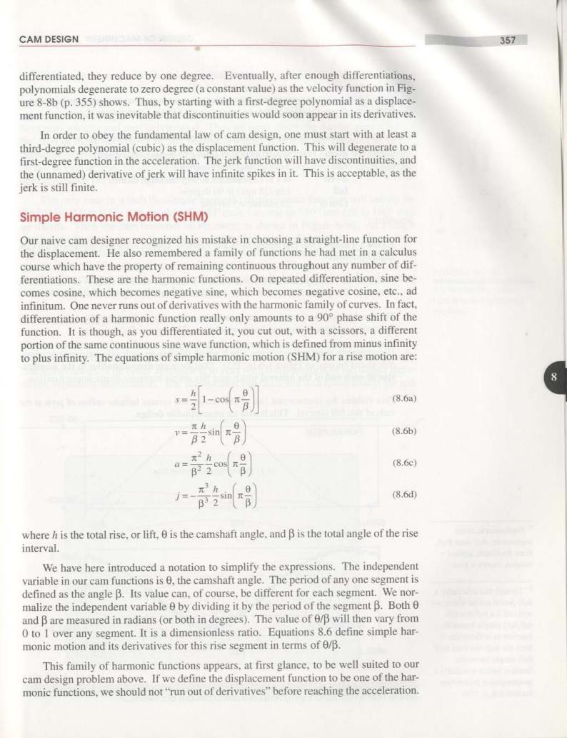
358 DESIGN OF MACHINERY CHAPTER 8 DEXAMPLE 8-2 Sophomoric Cam Design-Simple Harmonic Motion-Still a Bad Cam. Problem: Consider the same cam design CEP specification as in Example 8-1: dwell at zero displacement for 90 degrees (low dwell) rise 1 in(25 mm)in 90 degrees dwell at I in(25 mm)for 90 degrees (high dwell) fall 1 in(25 mm)in 90 degrees cam 0 2nt rad/sec I rev/sec Solution: 1 Figure 8-9 shows a full-rise simple harmonic function applied to the rise segment of our cam design problem. 2 Note that the velocity function is continuous,as it matches the zero velocity of the dwells at each end.The peak value is 6.28 in/sec (160 mm/sec)at the midpoint of the rise. 3 The acceleration function,however,is not continuous.It is a half-period cosine curve and has nonzero values at start and finish which are +78.8 in/sec2(2.0 m/sec2). 4 Unfortunately,the dwell functions.which adjoin this rise on each side,have zero accelera- tion as can be seen in Figure 8-6(p.353).Thus there are discontinuities in the accelera- 8 tion at each end of the interval which uses this simple harmonic displacement function. 5 This violates the fundamental law of cam design and creates infinite spikes of jerk at the ends of this fall interval.This is also an unacceptable design. svaj Plots for Simple Harmonic Rise .Sophomoric.from sophomore.def.wise fool. from the Greek.sophos wisdom.moros =fool. t Though this is actually a half-period cosine wave,we will call it a full-rise (or full-fall)simple harmonic function to differentiate it from the half-rise (and half- 22 78 90 fall)simple harmonic function which is actually a quarter-period cosine(see FIGURE 8-9 Section 8.6.p.385). Simple harmonic motion with dwells has discontinuous acceleration

CAM DESIGN 359 What went wrong?While it is true that harmonic functions are differentiable ad infinitum,we are not dealing here with single harmonic functions.Our cam function S=aCO5①t over the entire interval is a piecewise function,(Figure 8-6,p.353)made up of several segments,some of which may be dwell portions or other functions.A dwell will always have zero velocity and zero acceleration.Thus we must match the dwells'zero values at the ends of those derivatives of any nondwell segments that adjoin them.The simple harmonic displacement function,when used with dwells,does not satisfy the fundamen- tal law of cam design.Its second derivative,acceleration,is nonzero at its ends and thus does not match the dwells required in this example. The only case in which the simple harmonic displacement function will satisfy the fundamental law is the non-quick-return RF case,i.e.,rise in 180 and fall in 180 with no dwells.Then the cam becomes an eccentric as shown in Figure 8-10.As a single continuous (not piecewise)function,its derivatives are continuous also.Figure 8-11 shows the displacement(in inches)and acceleration functions (in g's)of the eccentric cam in Figure 8-10 as actually measured on the follower.The noise,or"ripple,"on the acceleration curve is due to small,unavoidable,manufacturing errors.Manufacturing FIGURE 8-10 limitations will be discussed in a later section. An eccentric cam has simple harmonic Cycloidal Displacement motion The two bad examples of cam design described above should lead the cam designer to the conclusion that consideration only of the displacement function when designing a cam is erroneous.The better approach is to start with consideration of the higher deriv- atives,especially acceleration.The acceleration function,and to a lesser extent the jerk 8 250.00 DISPLACEMENT -200.00. 0.0 REV 1.0000 2.0000 -3.0000. ACCELERATION 0.0 REV 1.0000 FIGURE 8-11 Displacement and acceleration as measured on the follower of an eccentric cam