
360 DESIGN OF MACHINERY CHAPTER 8 function.should be the principal concern of the designer.In some cases,especially when the mass of the follower train is large,or when there is a specification on velocity,that function must be carefully designed as well. With this in mind,we will redesign the cam for the same example specifications as above.This time we will start with the acceleration function.The harmonic family of functions still have advantages which make them attractive for these applications.Fig- ure 8-12 shows a full-period sinusoid applied as the acceleration function.It meets the constraint of zero magnitude at each end to match the dwell segments which adjoin it. The equation for a sine wave is: 8 a=Csin 2B) (8.7) We have again normalized the independent variable 0 by dividing it by the period of the segment B with both 0 and B measured in radians.The value of 0/B ranges from 0 to I over any segment and is a dimensionless ratio.Since we want a full-cycle sine wave, we must multiply the argument by 2n.The argument of the sine function will then vary between 0 and 2nt regardless of the value of B.The constant C defines the amplitude of the sine wave. Integrate to obtain velocity. 8 fw-fcun) (8.8) v=-CB 22 sva/Plots for Cycloidal Displacement Rise 22 45 78 90 FIGURE 8-12 Sinusoldal acceleration gives cycloidal displacement
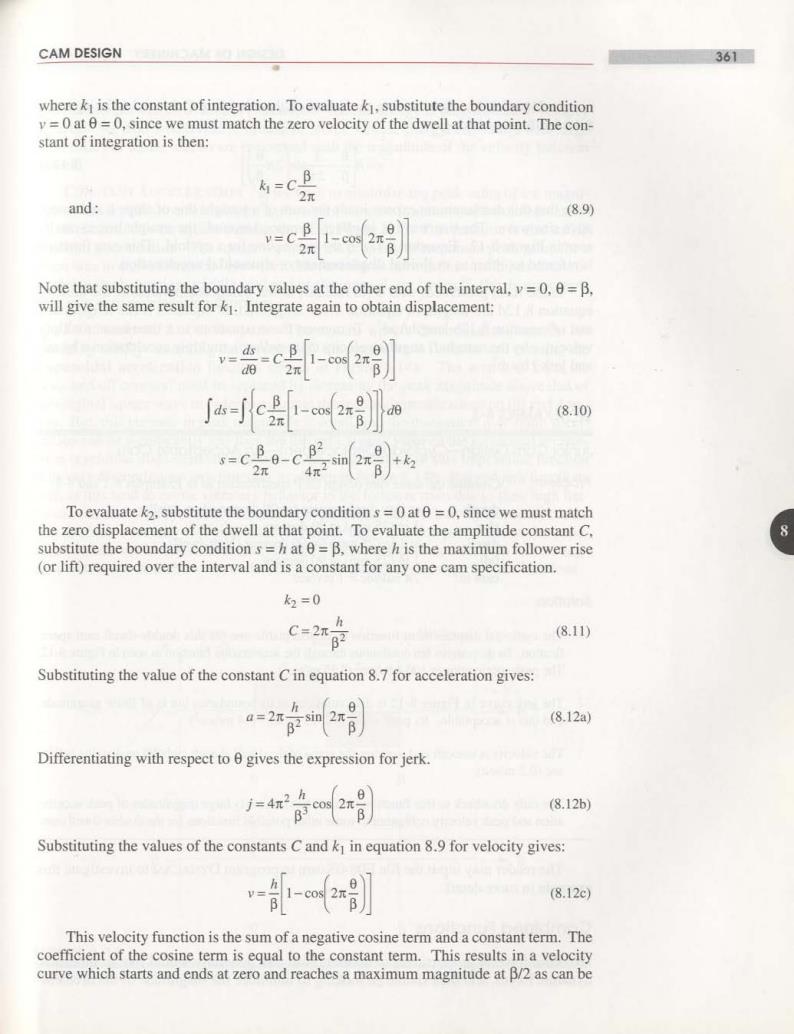
CAM DESIGN 361 where k is the constant of integration.To evaluate k,substitute the boundary condition y=0 at 0=0,since we must match the zero velocity of the dwell at that point.The con- stant of integration is then: k=C 2π and: (8.9) 2π -m Note that substituting the boundary values at the other end of the interval.v=0.0=B. will give the same result for k.Integrate again to obtain displacement: -c-别 ja可c-m (8.10) s-CB0-CB 2π 2}6 To evaluate k2,substitute the boundary condition s=0 at 0 =0,since we must match the zero displacement of the dwell at that point.To evaluate the amplitude constant C. 8 substitute the boundary condition s =h at 0=B,where h is the maximum follower rise (or lift)required over the interval and is a constant for any one cam specification. k2=0 h C=2 (8.11) Substituting the value of the constant C in equation 8.7 for acceleration gives: (8.12a) Differentiating with respect to 0 gives the expression for jerk. (8.12b) Substituting the values of the constants C and k in equation 8.9 for velocity gives: l (8.12c) This velocity function is the sum of a negative cosine term and a constant term.The coefficient of the cosine term is equal to the constant term.This results in a velocity curve which starts and ends at zero and reaches a maximum magnitude at B/2 as can be
362 DESIGN OF MACHINERY CHAPTER 8 seen in Figure 8-12.Substituting the values of the constants C,k.and k2 in equation 8.10 for displacement gives: 唱 (8.12d Note that this displacement expression is the sum of a straight line of slope h and a neg- ative sine wave.The sine wave is,in effect."wrapped around"the straight line as can be seen in Figure 8-12.Equation 8.12d is the expression for a cycloid.This cam function is referred to either as cycloidal displacement or sinusoidal acceleration In the form presented,with 0(in radians)as the independent variable,the units of equation 8.12d are length.of equation 8.12c length/rad,of equation 8.12a length/rad2, and of equation 8.12b length/rad-.To convert these equations to a time base,multiply velocity v by the camshaft angular velocity co(in rad/sec),multiply acceleration a by o2, and jerk j by c. EXAMPLE 8-3 Junior Cam Design-Cycloidal Displacement-An Acceptable Cam. Problem: Consider the same cam design CEP specification as in Examples 8-1 and 8-2: dwell at zero displacement for 90 degrees (low dwell) rise 1 in (25 mm)in 90 degrees dwell at I in(25 mm)for 90 degrees(high dwell) fall I in (25 mm)in 90 degrees cam o 2nt rad/sec 1 rev/sec Solution: 1 The cycloidal displacement function is an acceptable one for this double-dwell cam speci- fication.Its derivatives are continuous through the acceleration function as seen in Figure 8-12. The peak acceleration is 100.4 in/sec2(2.55 m/sec2). 2 The jerk curve in Figure 8-12 is discontinuous at its boundaries but is of finite magnitude, and this is acceptable.Its peak value is 2523 in/sec3(64 m/sec3). 3 The velocity is smooth and matches the zeros of the dwell at each end.Its peak value is 8 in/ sec (0.2 m/sec). 4 The only drawback to this function is that it has relatively large magnitudes of peak acceler- ation and peak velocity compared to some other possible functions for the double-dwell case. The reader may input the file E08-03.cam to program DYNACAM to investigate this example in more detail. Combined Functions Dynamic force is proportional to acceleration.We generally would like to minimize dynamic forces,and thus should be looking to minimize the magnitude of the accelera-

CAM DESIGN 363 tion function as well as to keep it continuous.Kinetic energy is proportional to velocity squared.We also would like to minimize stored kinetic energy,especially with large mass follower trains,and so are concerned with the magnitude of the velocity function as well. CONSTANT ACCELERATION If we wish to minimize the peak value of the magni- tude of the acceleration function for a given problem,the function that would best satis- fy this constraint is the square wave as shown in Figure 8-13.This function is also called constant acceleration.The square wave has the property of minimum peak value for a given area in a given interval.However,this function is not continuous.It has disconti- nuities at the beginning,middle,and end of the interval,so,by itself,this is unaccept- able as a cam acceleration function. TRAPEZOIDAL ACCELERATION The square wave's discontinuities can be re- moved by simply"knocking the corners off the square wave function and creating the trapezoidal acceleration function shown in Figure 8-14a.The area lost from the "knocked off corners"must be replaced by increasing the peak magnitude above that of the original square wave in order to maintain the required specifications on lift and dura- tion.But,this increase in peak magnitude is small,and the theoretical maximum accel- eration can be significantly less than the theoretical peak value of the sinusoidal acceler- ation(cycloidal displacement)function.One disadvantage of this trapezoidal function is its very discontinuous jerk function,as shown in Figure 8-14b.Ragged jerk functions such as this tend to excite vibratory behavior in the follower train due to their high har- monic content.The cycloidal's sinusoidal acceleration has a relatively smoother cosine jerk function with only two discontinuities in the interval and is preferable to the trape- zoid's square waves of jerk.But the cycloidal's theoretical peak acceleration will be larg- er.which is not desirable.So,trade-offs must be made in selecting the cam functions. Low dwell Rise High dwell d (a) 0 G min 0 (b) 0 0 FIGURE 8-13 Constant acceleration glves infinite jerk
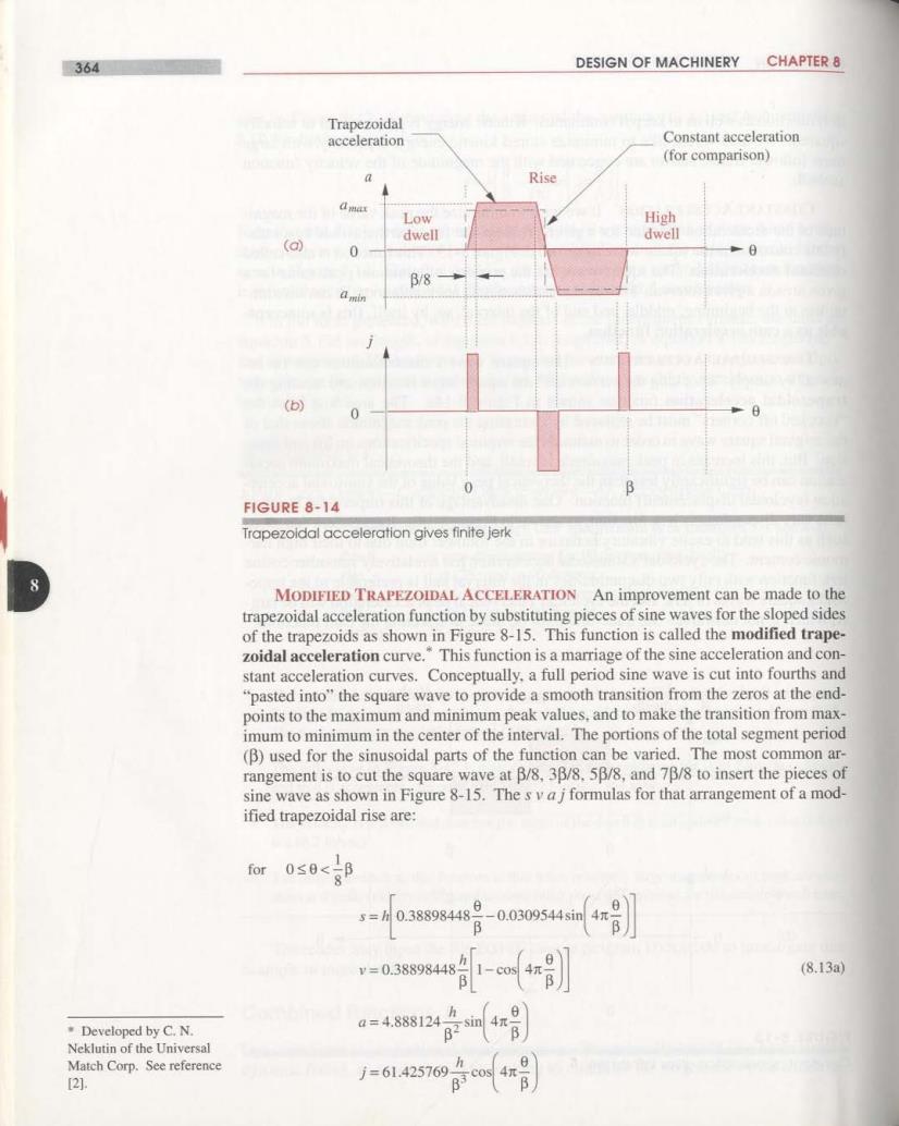
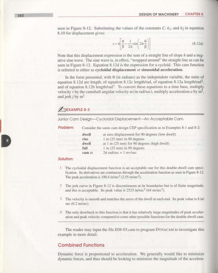
364 DESIGN OF MACHINERY CHAPTER 8 Trapezoidal acceleration Constant acceleration (for comparison) a Rise Low High dwell dwell (a) 0 B/8 (b) 0 0 FIGURE 8-14 Trapezoidal acceleration gives finite jerk 8 MODIFIED TRAPEZOIDAL ACCELERATION An improvement can be made to the trapezoidal acceleration function by substituting pieces of sine waves for the sloped sides of the trapezoids as shown in Figure 8-15.This function is called the modified trape- zoidal acceleration curve."This function is a marriage of the sine acceleration and con- stant acceleration curves.Conceptually,a full period sine wave is cut into fourths and "pasted into"the square wave to provide a smooth transition from the zeros at the end- points to the maximum and minimum peak values,and to make the transition from max- imum to minimum in the center of the interval.The portions of the total segment period (B)used for the sinusoidal parts of the function can be varied.The most common ar- rangement is to cut the square wave atβ/8,3β/8.5β/8,and7β/8 to insert the pieces of sine wave as shown in Figure 8-15.The s v aj formulas for that arrangement of a mod- ified trapezoidal rise are: 0≤0< s=M0.388984489-0.030954sin v=0.38898448 (8.13a) Developed by C.N. a=4.888124 Neklutin of the Universal Match Corp.See reference [2]. j=61.425769斤c0