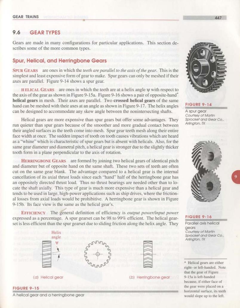
GEAR TRAINS 447 9.6 GEAR TYPES Gears are made in many configurations for particular applications.This section de- scribes some of the more common types. Spur,Helical,and Herringbone Gears SPUR GEARS are ones in which the teeth are parallel to the axis of the gear.This is the simplest and least expensive form of gear to make.Spur gears can only be meshed if their axes are parallel.Figure 9-14 shows a spur gear. HELICAL GEARS are ones in which the teeth are at a helix angle w with respect to the axis of the gear as shown in Figure 9-15a.Figure 9-16 shows a pair of opposite-hand" helical gears in mesh.Their axes are parallel.Two crossed helical gears of the same hand can be meshed with their axes at an angle as shown in Figure 9-17.The helix angles FIGURE 9-14 can be designed to accommodate any skew angle between the nonintersecting shafts. A spur gear Courtesy of Martin Helical gears are more expensive than spur gears but offer some advantages.They Sprocket and Gear Co. run quieter than spur gears because of the smoother and more gradual contact between Arlington,TX their angled surfaces as the teeth come into mesh.Spur gear teeth mesh along their entire face width at once.The sudden impact of tooth on tooth causes vibrations which are heard as a"whine"which is characteristic of spur gears but is absent with helicals.Also,for the same gear diameter and diametral pitch.a helical gear is stronger due to the slightly thicker tooth form in a plane perpendicular to the axis of rotation. HERRINGBONE GEARS are formed by joining two helical gears of identical pitch and diameter but of opposite hand on the same shaft.These two sets of teeth are often cut on the same gear blank.The advantage compared to a helical gear is the internal cancellation of its axial thrust loads since each"hand"half of the herringbone gear has an oppositely directed thrust load.Thus no thrust bearings are needed other than to lo- cate the shaft axially.This type of gear is much more expensive than a helical gear and tends to be used in large,high-power applications such as ship drives,where the friction- al losses from axial loads would be prohibitive.A herringbone gear is shown in Figure 9-15b.Its face view is the same as the helical gear's. EFFICIENCY The general definition of efficiency is ourput power/input power expressed as a percentage.A spur gearset can be 98 to 99%efficient.The helical gear- FIGURE 9-16 set is less efficient than the spur gearset due to sliding friction along the helix angle.They Parallel axis helical gears Helix Courtesy of Martin angle Sprocket and Gear Co.. Artington.TX Helical gears are cither right-or left-handed.Note that the gear of Figure (a)Helical gear (b)Herringbone gear 9-15a is left-handed because,if either face of FIGURE 9-15 the gear were placed on a horizontal surface,its teeth A helical gear and a herringbone gear would slope up to the left
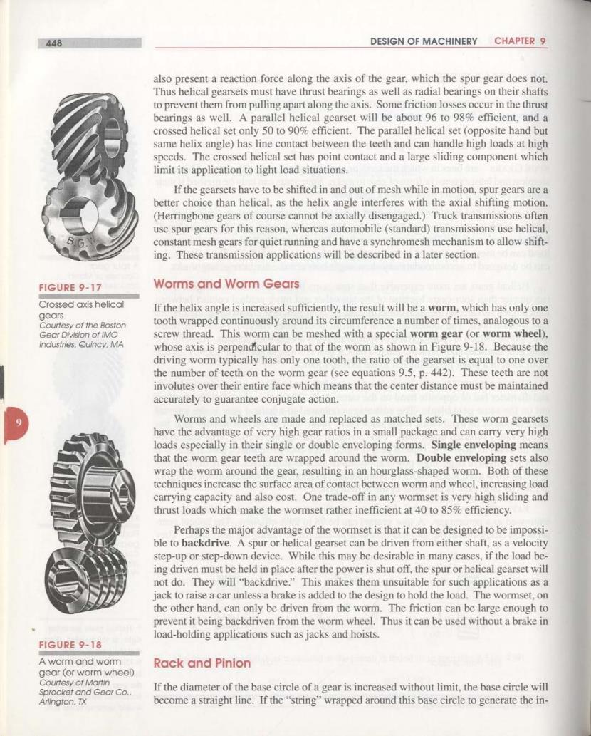
448 DESIGN OF MACHINERY CHAPTER 9 also present a reaction force along the axis of the gear.which the spur gear does not. Thus helical gearsets must have thrust bearings as well as radial bearings on their shafts to prevent them from pulling apart along the axis.Some friction losses occur in the thrust bearings as well.A parallel helical gearset will be about 96 to 98%efficient,and a crossed helical set only 50 to 90%efficient.The parallel helical set (opposite hand but same helix angle)has line contact between the teeth and can handle high loads at high speeds.The crossed helical set has point contact and a large sliding component which limit its application to light load situations. If the gearsets have to be shifted in and out of mesh while in motion,spur gears are a better choice than helical,as the helix angle interferes with the axial shifting motion (Herringbone gears of course cannot be axially disengaged.)Truck transmissions often use spur gears for this reason.whereas automobile(standard)transmissions use helical. constant mesh gears for quiet running and have a synchromesh mechanism to allow shift- ing.These transmission applications will be described in a later section FIGURE 9-17 Worms and Worm Gears Crossed axis helical If the helix angle is increased sufficiently,the result will be a worm,which has only one gears Courtesy of the Boston tooth wrapped continuously around its circumference a number of times,analogous to a Gear Division of IMO screw thread.This worm can be meshed with a special worm gear (or worm wheel). industries.Quincy,MA whose axis is perpendicular to that of the worm as shown in Figure 9-18.Because the driving worm typically has only one tooth,the ratio of the gearset is equal to one over the number of teeth on the worm gear(see equations 9.5,p.442).These teeth are not involutes over their entire face which means that the center distance must be maintained accurately to guarantee conjugate action. Worms and wheels are made and replaced as matched sets.These worm gearsets have the advantage of very high gear ratios in a small package and can carry very high loads especially in their single or double enveloping forms.Single enveloping means that the worm gear teeth are wrapped around the worm.Double enveloping sets also wrap the worm around the gear,resulting in an hourglass-shaped worm.Both of these techniques increase the surface area of contact between worm and wheel,increasing load carrying capacity and also cost.One trade-off in any wormset is very high sliding and thrust loads which make the wormset rather inefficient at 40 to 85%efficiency. Perhaps the major advantage of the wormset is that it can be designed to be impossi- ble to backdrive.A spur or helical gearset can be driven from either shaft,as a velocity step-up or step-down device.While this may be desirable in many cases,if the load be- ing driven must be held in place after the power is shut off,the spur or helical gearset will not do.They will "backdrive."This makes them unsuitable for such applications as a jack to raise a car unless a brake is added to the design to hold the load.The wormset,on the other hand,can only be driven from the worm.The friction can be large enough to prevent it being backdriven from the worm wheel.Thus it can be used without a brake in load-holding applications such as jacks and hoists. FIGURE 9-18 A worm and worm Rack and Pinion gear (or worm wheel) Courtesy of Martin Sprocket and Gear Co.. If the diameter of the base circle of a gear is increased without limit,the base circle will Arlington.TX become a straight line.If the"string"wrapped around this base circle to generate the in-
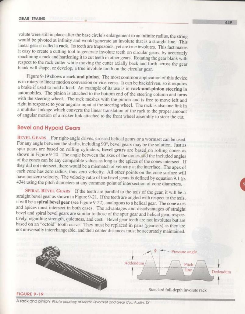
GEAR TRAINS 449 volute were still in place after the base circle's enlargement to an infinite radius,the string would be pivoted at infinity and would generate an involute that is a straight line.This linear gear is called a rack.Its teeth are trapezoids,yet are true involutes.This fact makes it easy to create a cutting tool to generate involute teeth on circular gears,by accurately machining a rack and hardening it to cut teeth in other gears.Rotating the gear blank with respect to the rack cutter while moving the cutter axially back and forth across the gear blank will shape,or develop,a true involute tooth on the circular gear. Figure 9-19 shows a rack and pinion.The most common application of this device is in rotary to linear motion conversion or vice versa.It can be backdriven,so it requires a brake if used to hold a load.An example of its use is in rack-and-pinion steering in automobiles.The pinion is attached to the bottom end of the steering column and turns with the steering wheel.The rack meshes with the pinion and is free to move left and right in response to your angular input at the steering wheel.The rack is also one link in a multibar linkage which converts the linear translation of the rack to the proper amount of angular motion of a rocker link attached to the front wheel assembly to steer the car. Bevel and Hypoid Gears BEVEL.GEARS For right-angle drives,crossed helical gears or a wormset can be used. For any angle between the shafts,including 90,bevel gears may be the solution.Just as spur gears are based on rolling cylinders,bevel gears are based on rolling cones as shown in Figure 9-20.The angle between the axes of the cones and the included angles of the cones can be any compatible values as long as the apices of the cones intersect.If they did not intersect,there would be a mismatch of velocity at the interface.The apex of each cone has zero radius.thus zero velocity.All other points on the cone surface will have nonzero velocity.The velocity ratio of the bevel gears is defined by equation 9.1(p. 434)using the pitch diameters at any common point of intersection of cone diameters. SPIRAL BEVEL GEARS If the teeth are parallel to the axis of the gear,it will be a straight bevel gear as shown in Figure 9-21.If the teeth are angled with respect to the axis, it will be a spiral bevel gear(see Figure 9-22).analogous to a helical gear.The cone axes and apices must intersect in both cases.The advantages and disadvantages of straight bevel and spiral bevel gears are similar to those of the spur gear and helical gear,respec- tively.regarding strength,quietness,and cost.Bevel gear teeth are not involutes but are based on an"octoid"tooth curve.They must be replaced in pairs(gearsets)as they are not universally interchangeable,and their center distances must be accurately maintained. Pressure angle Addendum Pitch line Dedendum Standard full-depth involute rack FIGURE 9-19 A rack and pinion Photo courtesy of Martin Sprocket and Gear Co..Austin.TX
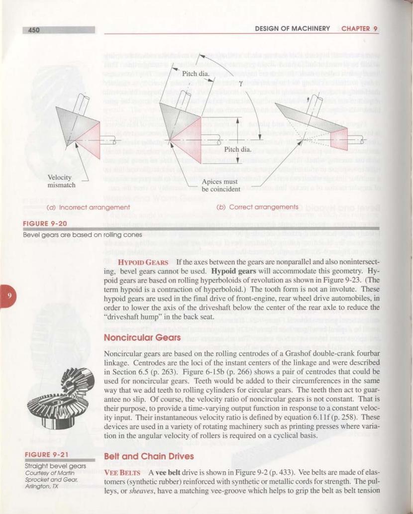
450 DESIGN OF MACHINERY CHAPTER 9 Pitch dia. Piteh dia. Velocity mismatch Apices must be coincident (a)Incorrect arrangement (b)Correct arrangements FIGURE 9-20 Bevel gears are based on rolling cones HYPOID GEARS If the axes between the gears are nonparallel and also nonintersect- ing.bevel gears cannot be used.Hypoid gears will accommodate this geometry.Hy- poid gears are based on rolling hyperboloids of revolution as shown in Figure 9-23.(The term hypoid is a contraction of hyperboloid.)The tooth form is not an involute.These hypoid gears are used in the final drive of front-engine,rear wheel drive automobiles,in order to lower the axis of the driveshaft below the center of the rear axle to reduce the “driveshaft hump'”in the back seat. Noncircular Gears Noncircular gears are based on the rolling centrodes of a Grashof double-crank fourbar linkage.Centrodes are the loci of the instant centers of the linkage and were described in Section 6.5(p.263).Figure 6-15b(p.266)shows a pair of centrodes that could be used for noncircular gears.Teeth would be added to their circumferences in the same way that we add teeth to rolling cylinders for circular gears.The teeth then act to guar- antee no slip.Of course,the velocity ratio of noncircular gears is not constant.That is their purpose,to provide a time-varying output function in response to a constant veloc- ity input.Their instantaneous velocity ratio is defined by equation 6.11f(p.258).These devices are used in a variety of rotating machinery such as printing presses where varia- tion in the angular velocity of rollers is required on a cyclical basis. FIGURE 9-21 Belt and Chain Drives Straight bevel gears Courtesy of Martin VEE BELTS A vee belt drive is shown in Figure 9-2(p.433).Vee belts are made of elas- Sprocket and Gear. tomers(synthetic rubber)reinforced with synthetic or metallic cords for strength.The pul- Arlington,TX leys,or sheaves,have a matching vee-groove which helps to grip the belt as belt tension