Instruction Manual and Experiment Guide MICROWAVE OPTICS Shanghai JiaoTong University Center of Physics Experiment
1 Instruction Manual and Experiment Guide MICROWAVE OPTICS Shanghai JiaoTong University Center of Physics Experiment
Table of Contents Sections Page Experiment 1:Introductionto the system............................... Experiment2:reflection................4 Experiment 3:Standing Waves-Measuring Wavelengths................6 Experiment 4:Refraction Through a Prism.................. …9 Experiment5:Polarization..........I Experiment6:Double-Slit Interference...............13 Experiment 7:Lloyd's Mirror....15 Experiment 8:Fabry-Perot Interferometer.......................... 17 Experiment 9:Michelson Interferometer....................... ..19 Experiment 10:Fiber Optics...................21 Experiment 11:Brewster's Angle........................ 22 Experiment 12:Bragg Diffraction..................................24
Table of Contents Sections Page Experiment 1: Introduction to the system……………………….……...1 Experiment 2: reflection…………………..……………………………4 Experiment 3: Standing Waves - Measuring Wavelengths…………….6 Experiment 4: Refraction Through a Prism……………………………9 Experiment 5: Polarization…………………………………………….11 Experiment 6: Double-Slit Interference……………………………….13 Experiment 7: Lloyd's Mirror………………………………………….15 Experiment 8: Fabry-Perot Interferometer…………………………….17 Experiment 9: Michelson Interferometer……………………………...19 Experiment 10: Fiber Optics…………………………………………..21 Experiment 11: Brewster’s Angle……………………………………..22 Experiment 12: Bragg Diffraction…………………………………….24
Experiment 1:Introduction to the system EQUIPMENT NEEDED: Transmitter -Goniometer -Receiver Reflector (1) Purpose This experiment gives a systematic introduction to the Microwave Optics System.This may prove helpful in learning to use the equipment effectively and in understanding the significance of measurements made with this equipment.It is however not a prerequisite to the following experiments. Procedure 1.Arrange the Transmitter and Receiver on the Goniometer as shown in Figure 1.I with the Transmitter attached to the fixed arm.Bc sure to adjust both Transmitter and Receiver to the same. 2.Plug in the Transmitter and turn the INTENSITY selection switch on the Receiver from OFF to 10X.(The LEDs should light up on both units. 3.Adjust the Transmitter and Receiver so the distance between the source diode in the Transmitter and the detector diode in the Receiver (the distance labeled R in Figure 1.1)is 40 cm (see Figure 1.2 for location of points of transmission and reception). The diodes are at the locations marked "T"and "R"on the bases. Figure 1.1 Equlpment Setup Adjust the INTENSITY and VARIABLE SENSITIVITY dials on the Receiver so that the meter reads 1.0(full scale). 4.Set the distance R to each of the values shown in Table 1.I.For each value of R,record the meter Effective Point of Emission of Effective Point of Reception of Transmitter Signal Transmitter Signal -5 cm- Transmitter Receiver Figure 1.2 Equipment Setup
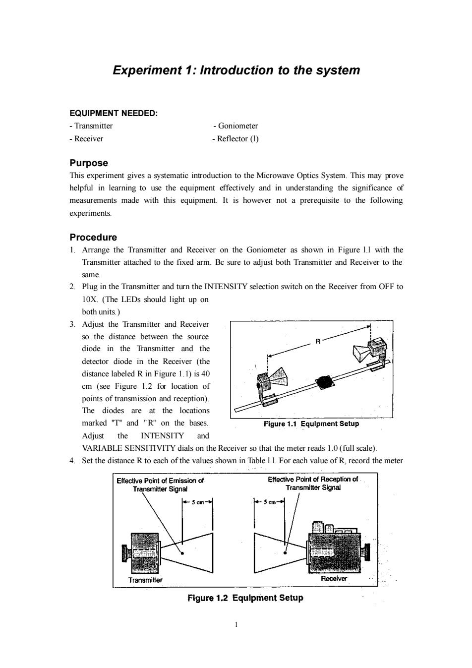
1 Experiment 1: Introduction to the system EQUIPMENT NEEDED: - Transmitter - Goniometer - Receiver - Reflector (l) Purpose This experiment gives a systematic introduction to the Microwave Optics System. This may prove helpful in learning to use the equipment effectively and in understanding the significance of measurements made with this equipment. It is however not a prerequisite to the following experiments. Procedure 1. Arrange the Transmitter and Receiver on the Goniometer as shown in Figure l.l with the Transmitter attached to the fixed arm. Bc sure to adjust both Transmitter and Receiver to the same. 2. Plug in the Transmitter and turn the INTENSITY selection switch on the Receiver from OFF to 10X. (The LEDs should light up on both units.) 3. Adjust the Transmitter and Receiver so the distance between the source diode in the Transmitter and the detector diode in the Receiver (the distance labeled R in Figure 1.1) is 40 cm (see Figure 1.2 for location of points of transmission and reception). The diodes are at the locations marked ''T'' and '`R'' on the bases. Adjust the INTENSITY and VARIABLE SENSITIVITY dials on the Receiver so that the meter reads 1.0 (full scale). 4. Set the distance R to each of the values shown in Table l.l. For each value of R, record the meter
Reading.(Do not adjust the Receiver controls between measurements.)After making the measurements,perform the calculations shown in the table. 5.Set R to some value between 70 and 90 cm.While watching the meter,slowly decrease the distance between the Transmitter and Receiver.Does the meter deflection increase steadily as the distance decreases? 6.Set R to between 50 and 90 cm.Move a Reflector,its plane parallel to the axis of the microwave beam,toward and away from the beam axis,as shown in Figure 1.2.Observe the meter readings.Can you explain your observations in steps 5 and 6?Don't worry if you can't; you will have a chance to investigate these phenomena more closely in Experiments 3 and 8, later in this manual.For now just be aware of the following: IMPORTANT:Reflections from nearby objects,including the table top,can affect the results of your microwave experiments.To reduce the effects of extraneous reflections,keep your experiment table clear of all objects,especially metal objects,other than those components required for the current experiment. 7.Loosen the hand screw on the back of the Receiver and rotate the Receiver as shown in Figure 1.3.This varies the polarity of maximum Handscrew detection.(Look into the receiver horn and notice the alignment of the detector diode.)Observe the meter readings through a full 360 degree rotation of the horn.A small mirror may be helpful to view the meter reading as the receiver is turned. At what polarity does the Receiver detect no signal? Flgure 1.3 Polarlzatlon Try rotating the Transmitter horn as well.When finished,reset the Transmitter and Receiver so their polarities match (e.g,both horns are horizontal or both horns are vertical). 8.Position the Transmitter so the output surface of the horn is centered directly over the center of the Degree Plate of the Goniometer arm (see Figure 1.4).With the Receiver directly facing the Transmitter and as far back on the Goniometer arm Figure 1.4 Signal Distribution as possible,adjust the Receiver controls for a meter reading of 1.0.Then rotate the rotatable arm of the Goniometer as shown in the figure.Set the angle of rotation(measured relative to the 180 degree point on the degree scale)to each of the values shown in Table 1.2,and record the meter reading at each setting. Angle Meter Reading Angle Meter Reading 0 1.0 50 0 60 20 70 3 80 40 90 Table 1.2 2
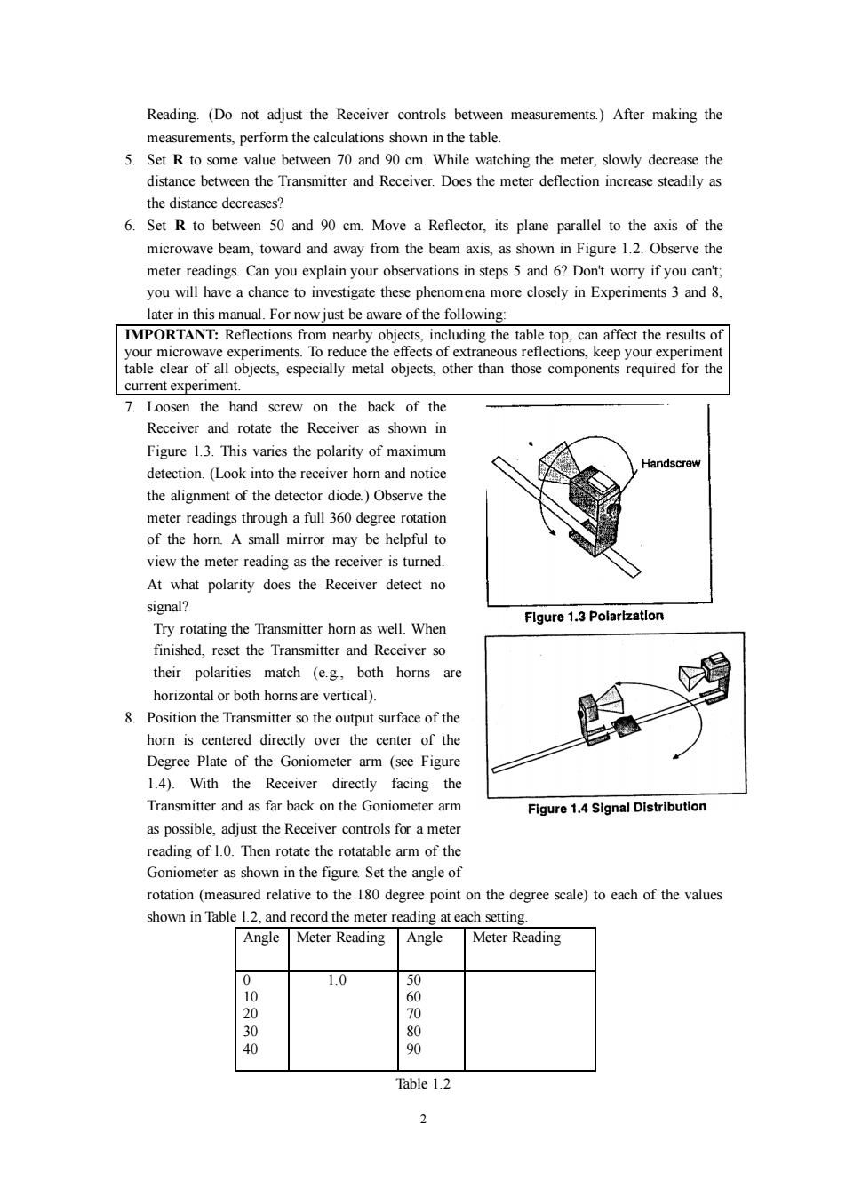
2 Reading. (Do not adjust the Receiver controls between measurements.) After making the measurements, perform the calculations shown in the table. 5. Set R to some value between 70 and 90 cm. While watching the meter, slowly decrease the distance between the Transmitter and Receiver. Does the meter deflection increase steadily as the distance decreases? 6. Set R to between 50 and 90 cm. Move a Reflector, its plane parallel to the axis of the microwave beam, toward and away from the beam axis, as shown in Figure 1.2. Observe the meter readings. Can you explain your observations in steps 5 and 6? Don't worry if you can't; you will have a chance to investigate these phenomena more closely in Experiments 3 and 8, later in this manual. For now just be aware of the following: IMPORTANT: Reflections from nearby objects, including the table top, can affect the results of your microwave experiments. To reduce the effects of extraneous reflections, keep your experiment table clear of all objects, especially metal objects, other than those components required for the current experiment. 7. Loosen the hand screw on the back of the Receiver and rotate the Receiver as shown in Figure 1.3. This varies the polarity of maximum detection. (Look into the receiver horn and notice the alignment of the detector diode.) Observe the meter readings through a full 360 degree rotation of the horn. A small mirror may be helpful to view the meter reading as the receiver is turned. At what polarity does the Receiver detect no signal? Try rotating the Transmitter horn as well. When finished, reset the Transmitter and Receiver so their polarities match (e.g., both horns are horizontal or both horns are vertical). 8. Position the Transmitter so the output surface of the horn is centered directly over the center of the Degree Plate of the Goniometer arm (see Figure 1.4). With the Receiver directly facing the Transmitter and as far back on the Goniometer arm as possible, adjust the Receiver controls for a meter reading of l.0. Then rotate the rotatable arm of the Goniometer as shown in the figure. Set the angle of rotation (measured relative to the 180 degree point on the degree scale) to each of the values shown in Table l.2, and record the meter reading at each setting. Angle Meter Reading Angle Meter Reading 0 10 20 30 40 1.0 50 60 70 80 90 Table 1.2
Questions 1.The electric field of an electromagnetic wave is inversely proportional to the distance from the wave source (ie.,E =I/R).Use your data from step 4 of the experiment to determine if the meter reading of the Receiver is directly proportional to the electric field of the wave. 2.The intensity of an electromagnetic wave is inversely proportional to the square of the distance from the wave source (i.e.,I=1/R2).Use your data from step 4 of the experiment to determine if the meter reading of the Receiver is directly proportional to the intensity of the wave. 3.Considering your results in step 7,to what extent can the Transmitter output be considered a spherical wave?-A plane wave?
3 Questions 1. The electric field of an electromagnetic wave is inversely proportional to the distance from the wave source (i.e., E = l/R). Use your data from step 4 of the experiment to determine if the meter reading of the Receiver is directly proportional to the electric field of the wave. 2. The intensity of an electromagnetic wave is inversely proportional to the square of the distance from the wave source (i.e., 2 I = 1/ R ). Use your data from step 4 of the experiment to determine if the meter reading of the Receiver is directly proportional to the intensity of the wave. 3. Considering your results in step 7, to what extent can the Transmitter output be considered a spherical wave? - A plane wave?