
Instruction Manual and Experiment Guide AC/DC ELECTRONICS LABORATORY Shanghai JiaoTong University Center of Physics Experiment
Instruction Manual and Experiment Guide AC/DC ELECTRONICS LABORATORY Shanghai JiaoTong University Center of Physics Experiment
Table of contents Section Page Experiment 1:Circuits Experiment Board........................... Experiment 2:Light in Circuits........... .3 Experiment3:Ohm's Law......... .5 Experiment4:Resistances in Circuits..... Experiment 5:Voltages in Circuits...... 11 Experiment6:Currents in Circuits... 15 Experiment 7:Kirchhoff's Rules......... 17 Experiment 8:Capacitors in Circuits........ 19 Experiment9:Diodes................... 21 Experiment 10:Transistors...... 23 Experiment 11:Ohm's Law II RC Circuit. 25 Experiment 12:LR Circuit.......... 32 Experiment 13:Diode Lab-Part I........ .37 Experiment 14:LRC Circuit.................. 42 Experiment 15:Diode Lab-Part 2......... 49 Experiment 16:Transistor Lab 1-The NPN... .57 Experiment 17:Transistor as a Digital Switch......... 73 Experiment 18:Transistor Lab 2-Current Gain:The NPN Emitter Follower Amplifier............ .80
Table of contents Section Page Experiment 1: Circuits Experiment Board.……………………………...1 Experiment 2: Light in Circuits…………………………………….…....3 Experiment 3: Ohm's Law………………………………………………..5 Experiment 4: Resistances in Circuits………………..…………………..7 Experiment 5: Voltages in Circuits…………………….…………………11 Experiment 6: Currents in Circuits…………………………………..…...15 Experiment 7: Kirchhoff's Rules…………………………………………17 Experiment 8: Capacitors in Circuits……………………………….……19 Experiment 9: Diodes…………………………………………………….21 Experiment 10:Transistors……………………………………………….23 Experiment 11:Ohm’s Law II RC Circuit….…………………………….25 Experiment 12:LR Circuit .………………………………………………32 Experiment 13: Diode Lab - Part I….…………………………………….37 Experiment 14:LRC Circuit……………………………..……………….42 Experiment 15: Diode Lab - Part 2……………………………………….49 Experiment 16:Transistor Lab 1-The NPN………………...…………….57 Experiment 17:Transistor as a Digital Switch……………………………73 Experiment 18:Transistor Lab 2-Current Gain:The NPN Emitter Follower Amplifier………………………………………80
Experiment 19:Transistor Lab 3-Common-Emitter Amplifier............. 86 Experiment 20:Induction-Magnet througha Coil...........................93
Experiment 19:Transistor Lab 3 -Common-Emitter Amplifier………….86 Experiment 20:Induction -Magnet through a Coil..…………………….93
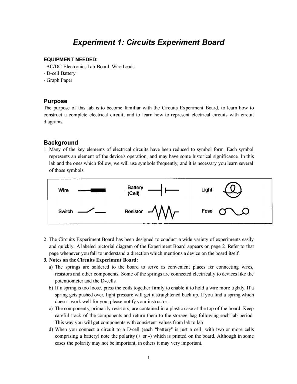
Experiment 1:Circuits Experiment Board EQUIPMENT NEEDED: -AC/DC Electronics Lab Board.Wire Leads -D-cell Battery -Graph Paper Purpose The purpose of this lab is to become familiar with the Circuits Experiment Board,to learn how to construct a complete electrical circuit,and to learn how to represent electrical circuits with circuit diagrams. Background 1.Many of the key elements of electrical circuits have been reduced to symbol form.Each symbol represents an element of the device's operation,and may have some historical significance.In this lab and the ones which follow,we will use symbols frequently,and it is necessary you learn several of those symbols. Wire Battery Light (Cell) Switch Resistor Fuse 2.The Circuits Experiment Board has been designed to conduct a wide variety of experiments easily and quickly.A labeled pictorial diagram of the Experiment Board appears on page 2.Refer to that page whenever you fall to understand a direction which mentions a device on the board itself. 3.Notes on the Circuits Experiment Board: a)The springs are soldered to the board to serve as convenient places for connecting wires, resistors and other components.Some of the springs are connected electrically to devices like the potentiometer and the D-cells. b)If a spring is too loose,press the coils together firmly to enable it to hold a wire more tightly.If a spring gets pushed over,light pressure will get it straightened back up.If you find a spring which doesn't work well for you,please notify your instructor. c)The components,primarily resistors,are contained in a plastic case at the top of the board.Keep careful track of the components and return them to the storage bag following each lab period. This way you will get components with consistent values from lab to lab. d)When you connect a circuit to a D-cell (each "battery"is just a cell,with two or more cells comprising a battery)note the polarity(+or-)which is printed on the board.Although in some cases the polarity may not be important,in others it may very important
1 Experiment 1: Circuits Experiment Board EQUIPMENT NEEDED: - AC/DC Electronics Lab Board. Wire Leads - D-cell Battery - Graph Paper Purpose The purpose of this lab is to become familiar with the Circuits Experiment Board, to learn how to construct a complete electrical circuit, and to learn how to represent electrical circuits with circuit diagrams. Background 1. Many of the key elements of electrical circuits have been reduced to symbol form. Each symbol represents an element of the device's operation, and may have some historical significance. In this lab and the ones which follow, we will use symbols frequently, and it is necessary you learn several of those symbols. 2. The Circuits Experiment Board has been designed to conduct a wide variety of experiments easily and quickly. A labeled pictorial diagram of the Experiment Board appears on page 2. Refer to that page whenever you fall to understand a direction which mentions a device on the board itself. 3. Notes on the Circuits Experiment Board: a) The springs are soldered to the board to serve as convenient places for connecting wires, resistors and other components. Some of the springs are connected electrically to devices like the potentiometer and the D-cells. b) If a spring is too loose, press the coils together firmly to enable it to hold a wire more tightly. If a spring gets pushed over, light pressure will get it straightened back up. If you find a spring which doesn't work well for you, please notify your instructor. c) The components, primarily resistors, are contained in a plastic case at the top of the board. Keep careful track of the components and return them to the storage bag following each lab period. This way you will get components with consistent values from lab to lab. d) When you connect a circuit to a D-cell (each “battery'' is just a cell, with two or more cells comprising a battery) note the polarity (+ or -) which is printed on the board. Although in some cases the polarity may not be important, in others it may very important
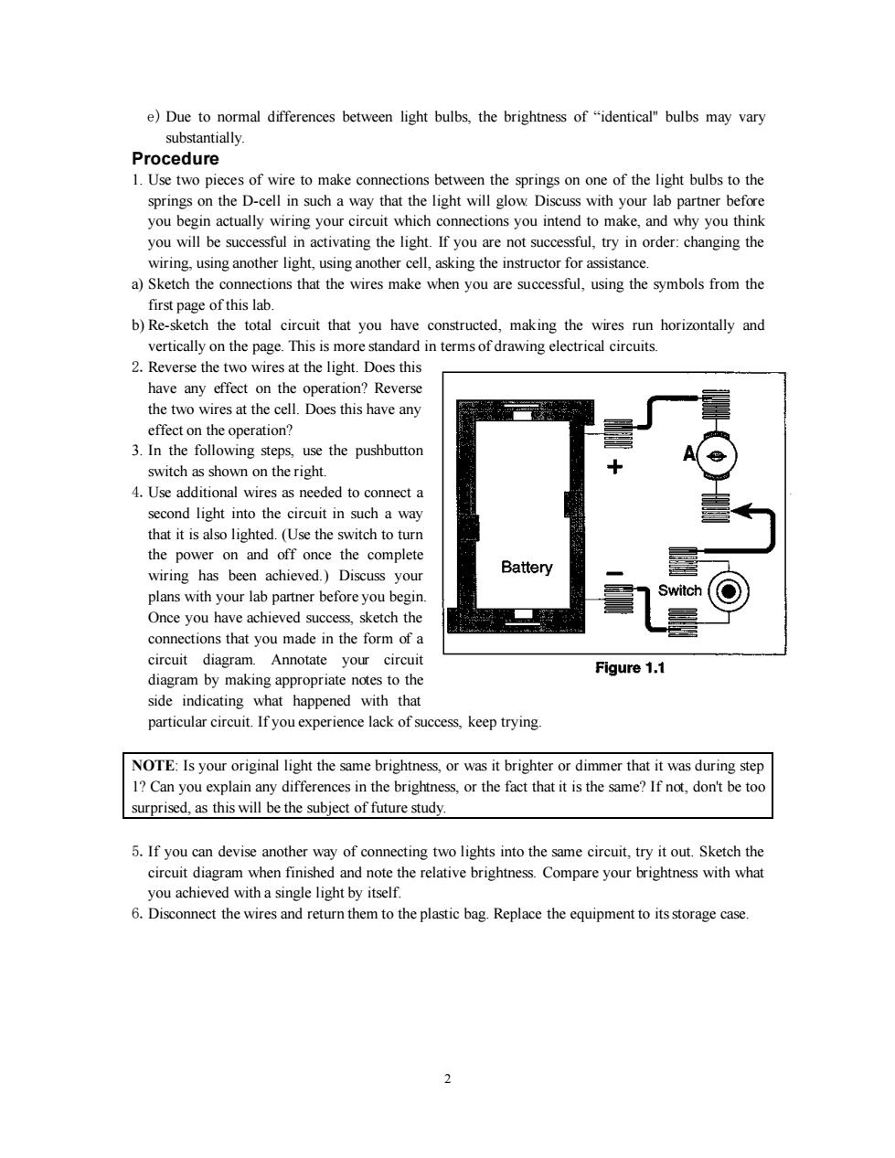
e)Due to normal differences between light bulbs,the brightness of"identical"bulbs may vary substantially. Procedure 1.Use two pieces of wire to make connections between the springs on one of the light bulbs to the springs on the D-cell in such a way that the light will glow Discuss with your lab partner before you begin actually wiring your circuit which connections you intend to make,and why you think you will be successful in activating the light.If you are not successful,try in order:changing the wiring,using another light,using another cell,asking the instructor for assistance. a)Sketch the connections that the wires make when you are successful,using the symbols from the first page of this lab. b)Re-sketch the total circuit that you have constructed,making the wires run horizontally and vertically on the page.This is more standard in terms of drawing electrical circuits. 2.Reverse the two wires at the light.Does this have any effect on the operation?Reverse the two wires at the cell.Does this have any effect on the operation? 3.In the following steps,use the pushbutton switch as shown on the right. 4.Use additional wires as needed to connect a second light into the circuit in such a way that it is also lighted.(Use the switch to turn the power on and off once the complete wiring has been achieved.)Discuss your Battery plans with your lab partner before you begin. Switch Once you have achieved success,sketch the connections that you made in the form of a circuit diagram.Annotate your circuit Figure 1.1 diagram by making appropriate notes to the side indicating what happened with that particular circuit.If you experience lack of success,keep trying. NOTE:Is your original light the same brightness,or was it brighter or dimmer that it was during step 1?Can you explain any differences in the brightness,or the fact that it is the same?If not,don't be too surprised,as this will be the subject of future study. 5.If you can devise another way of connecting two lights into the same circuit,try it out.Sketch the circuit diagram when finished and note the relative brightness.Compare your brightness with what you achieved with a single light by itself. 6.Disconnect the wires and return them to the plastic bag.Replace the equipment to its storage case. 2
2 e) Due to normal differences between light bulbs, the brightness of “identical'' bulbs may vary substantially. Procedure 1. Use two pieces of wire to make connections between the springs on one of the light bulbs to the springs on the D-cell in such a way that the light will glow. Discuss with your lab partner before you begin actually wiring your circuit which connections you intend to make, and why you think you will be successful in activating the light. If you are not successful, try in order: changing the wiring, using another light, using another cell, asking the instructor for assistance. a) Sketch the connections that the wires make when you are successful, using the symbols from the first page of this lab. b) Re-sketch the total circuit that you have constructed, making the wires run horizontally and vertically on the page. This is more standard in terms of drawing electrical circuits. 2.Reverse the two wires at the light. Does this have any effect on the operation? Reverse the two wires at the cell. Does this have any effect on the operation? 3. In the following steps, use the pushbutton switch as shown on the right. 4.Use additional wires as needed to connect a second light into the circuit in such a way that it is also lighted. (Use the switch to turn the power on and off once the complete wiring has been achieved.) Discuss your plans with your lab partner before you begin. Once you have achieved success, sketch the connections that you made in the form of a circuit diagram. Annotate your circuit diagram by making appropriate notes to the side indicating what happened with that particular circuit. If you experience lack of success, keep trying. NOTE: Is your original light the same brightness, or was it brighter or dimmer that it was during step 1? Can you explain any differences in the brightness, or the fact that it is the same? If not, don't be too surprised, as this will be the subject of future study. 5.If you can devise another way of connecting two lights into the same circuit, try it out. Sketch the circuit diagram when finished and note the relative brightness. Compare your brightness with what you achieved with a single light by itself. 6.Disconnect the wires and return them to the plastic bag. Replace the equipment to its storage case