Instruction Manual and Experiment Guide EDUCATIONAL SPECTROPHOTOMETER ACCESSORY KIT AND EDUCATIONAL SPECTROPHOTOMETER SYSTEM Shanghai JiaoTong University Center of Physics Experiment
Instruction Manual and Experiment Guide EDUCATIONAL SPECTROPHOTOMETER ACCESSORY KIT AND EDUCATIONAL SPECTROPHOTOMETER SYSTEM Shanghai JiaoTong University Center of Physics Experiment
Table of Contents Sections Page Quick Start..…… Introduction.... 52 Setup.……… …6 Procedures.….… 13 Activities Activity 1:EmissionSpectrum.......18 Activity 2:Absorption Spectrum....................................... 3
Table of Contents Sections Page Quick Start…………………………………………………………. 1 Introduction…………………………………………………………3 Setup……………………………………………………………….. 6 Procedures…………………………………………………………..13 Activities Activity 1:Emission Spectrum…………………………………... 18 Activity 2:Absorption Spectrum…………………………………23
Quick Start The following pages give an overview of the Spectrophotometer equipment setup. Step One:Prepare the Rotary Motion Sensor Step Three:Attach the Rotary Motion Sensor by removing the thumbscrew,three-step pulley, to the Base hinge with the two small and rod clamp. thumbscrews and attach the Pinion to the Rotary Motion Sensor shaft. thumbscrew Spectrophotometer Base three-step pulley Put the Pinion on行e shaft. Rotary Motion Sensor rod clamp attach Quick Start 3:Attach the Sensor and Pinion Quick Start 1:Prepare Rotary Motion Sensor Step Four:Put the Degree Plate/Light Sensor Step Two:Prepare the Spectrophotometer Arm on the Base.Attach the Grating Mount. Base by removing the two small thumbscrews Light Sensor Mount and Light Sensor. and Pinion and by rotating the hinge away Position the Focusing Lens from the Base. Light Sensor Light Sensor Mount with Aperture Disk and Scroen Focusing Lens Spectrophotometer Base Grating Mount Light Remove the Senso post Pinion 0. e the Quick Start 2:Prepare the Hinge mbs wing nu Qulck Start 4:D Plate Light Se Grating Mount, Focusing Lens,Light S nt,and Lignt Sensor
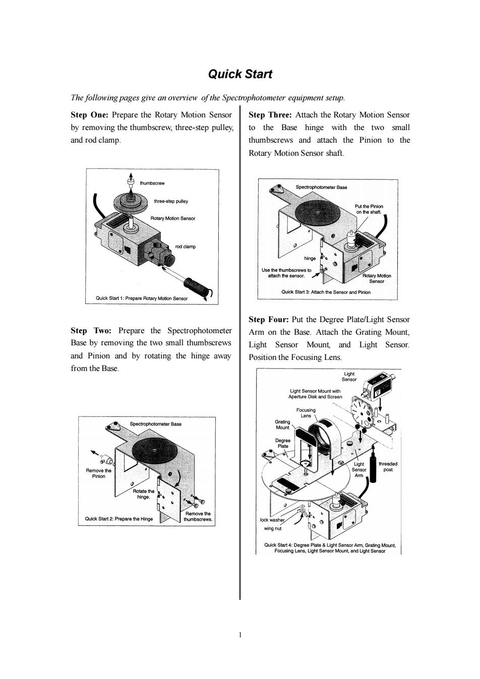
1 Quick Start The following pages give an overview of the Spectrophotometer equipment setup. Step One: Prepare the Rotary Motion Sensor by removing the thumbscrew, three-step pulley, and rod clamp. Step Two: Prepare the Spectrophotometer Base by removing the two small thumbscrews and Pinion and by rotating the hinge away from the Base. Step Three: Attach the Rotary Motion Sensor to the Base hinge with the two small thumbscrews and attach the Pinion to the Rotary Motion Sensor shaft. Step Four: Put the Degree Plate/Light Sensor Arm on the Base. Attach the Grating Mount, Light Sensor Mount, and Light Sensor. Position the Focusing Lens
Step Five:Put the Spectrophotometer Base Step Eight:Set up the experiment in the onto one end of the Optics Bench Science Workshop program. 1.Select the Light Sensor for Analog Channel 2.Select the Rotary Motion Sensor for Digital Channels 1 and 2. Base hinge 3.Set the Rotary Motion Sensor to high resolution (1440 Divisions/Rotation). 4.Create a calculation for "Actual Angular Position"based on the Angular Position T-slot Optics Bench square nut Quick Start 5:Put Base onto Optics Bench data from the Rotary Motion Sensor and the ratio of the radius of the Degree Plate to the radius of the small post on the Pinion Step Six:Mount the Collimating Slits and (typically,a 60 to 1 ratio). Collimating Lens onto the Optics Bench.Set 5.Select a Graph display.Set the vertical axis up a light source.Adjust the Collimating Slits to Light Intensity and the horizontal axis to and Collimating Lens to collimate the light your calculation of "Actual Angular beam. Position” 6.Set the sampling rate to 20 Hz (20 measurements per second). light Collimating source Lens Step Nine:Scan the Spectrum 1.Mask or hood the light source if necessary. Collimating light ray 2.Move the Light Sensor Arm so the Light Slits path Sensor is beyond the edge of the first order Quick Start 6:Setup for Collimation spectral pattern. 3.Start recording data.Slowly and continuously scan the spectrum.Scan the Step Seven:Attach the Grating to the mount so the glass side of the Grating faces the light first order spectrum on one side of the central ray,through the central ray,and source. through the first order spectrum on the other glass side faces light source Scan slowly and continuously in one direction. central ray first order spectral lines (zeroth order) first order spectral lines Quick ch the Grating Quick Start 9:Scan the Spectrum CAUTION:Avoid touching the Grating surface. side Step Ten:Analyze Your Data 2
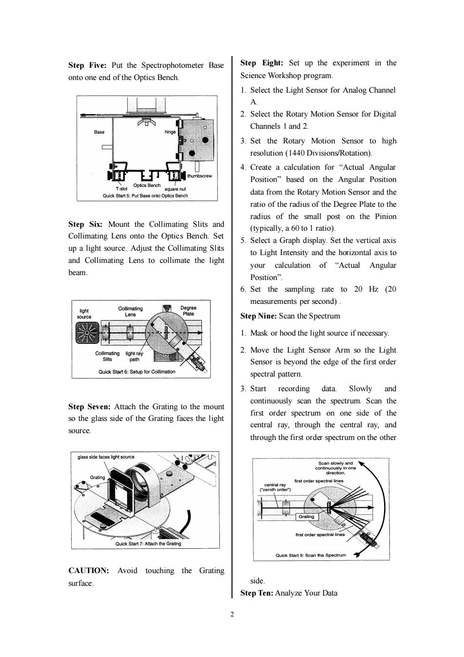
2 Step Five: Put the Spectrophotometer Base onto one end of the Optics Bench. Step Six: Mount the Collimating Slits and Collimating Lens onto the Optics Bench. Set up a light source. Adjust the Collimating Slits and Collimating Lens to collimate the light beam. Step Seven: Attach the Grating to the mount so the glass side of the Grating faces the light source. CAUTION: Avoid touching the Grating surface. Step Eight: Set up the experiment in the Science Workshop program. 1. Select the Light Sensor for Analog Channel A. 2. Select the Rotary Motion Sensor for Digital Channels 1 and 2. 3. Set the Rotary Motion Sensor to high resolution (1440 Divisions/Rotation). 4. Create a calculation for “Actual Angular Position” based on the Angular Position data from the Rotary Motion Sensor and the ratio of the radius of the Degree Plate to the radius of the small post on the Pinion (typically, a 60 to 1 ratio). 5. Select a Graph display. Set the vertical axis to Light Intensity and the horizontal axis to your calculation of “Actual Angular Position”. 6. Set the sampling rate to 20 Hz (20 measurements per second) . Step Nine: Scan the Spectrum 1. Mask or hood the light source if necessary. 2. Move the Light Sensor Arm so the Light Sensor is beyond the edge of the first order spectral pattern. 3. Start recording data. Slowly and continuously scan the spectrum. Scan the first order spectrum on one side of the central ray, through the central ray, and through the first order spectrum on the other side. Step Ten: Analyze Your Data
Introduction About This Manual This manual describes the PASCO OS-8537 Educational Spectrophotometer Accessory Kit and the PASCO OS-8539 Educational Spectrophotometer System.The OS-8537 Accessory Kit is designed to be mounted on the Optics Bench of the OS-8515 Basic Optics System. Components of the Kit The OS-8537 Educational Spectrophotometer Accessory Kit(see Figure la)includes the following items: Spectrophotometer Base Degree Plate with Light Sensor Arm Grating Mount Grating(~600 lines per mm) Focusing Lens Collimating Lens Collimating Slits Cuvettes (2) Rod Stand Mounting Brackets(2) Grating Degree Plate Grating Mount Light Sensor Amm Spectrophotometer Base Rod Stand Mo nting Clamps (2) Pinion' Collimating Slits Cuvettes (2) Focusing Lens Figure 1a:Educational Spectrophotometer Accessory Kit (*The pinion shown in Figure la can be mounted on a post on the Spectrophotometer Base when not in use. Recommended Equipment for use with the Spectrophotometer Accessory Kit: Basic Optics System(OS-8515) High Sensitivity Light Sensor(CI-6604) Aperture Bracket(OS-8534) Rotary Motion Sensor(CI-6538) Components of the System 3
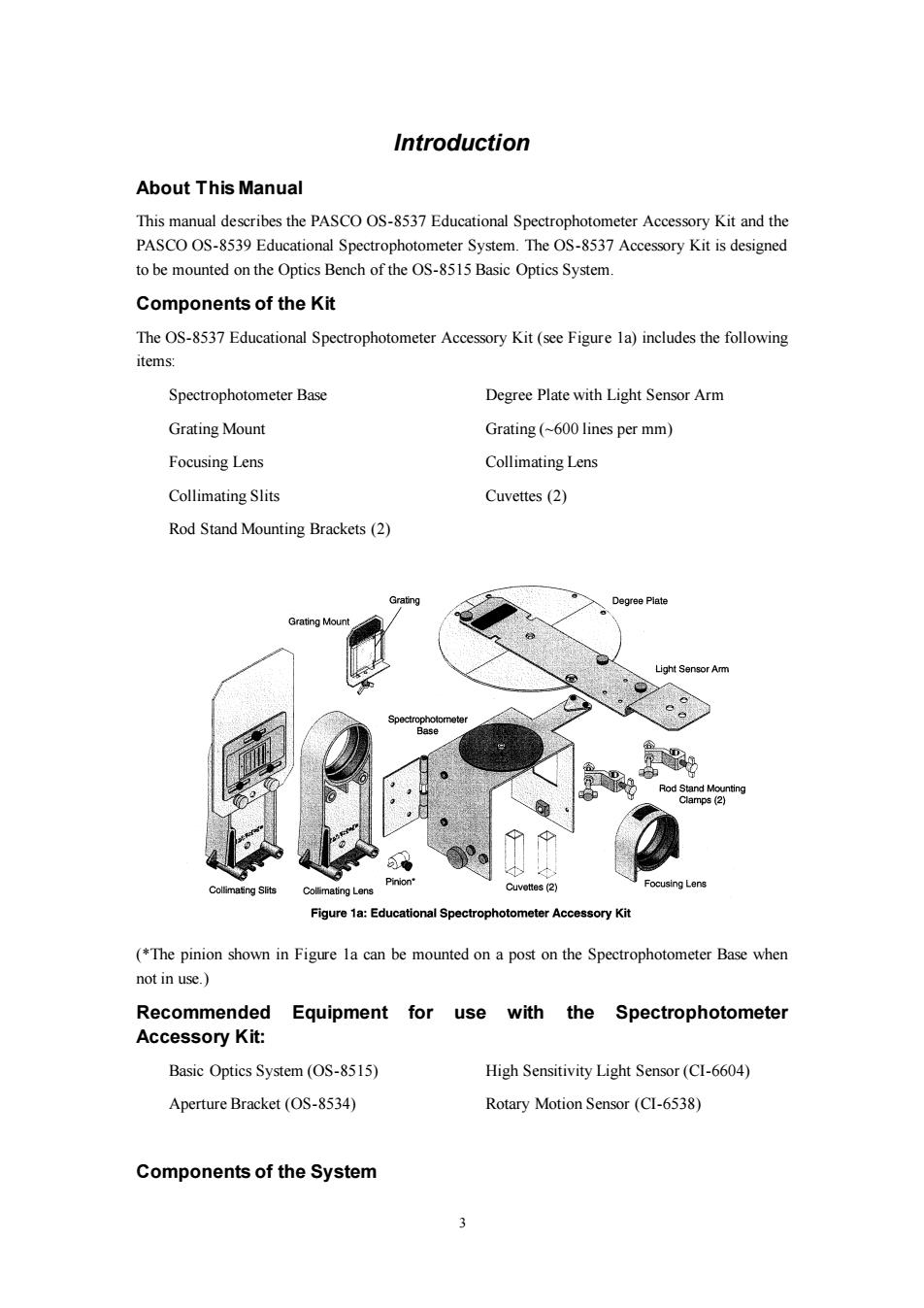
3 Introduction About This Manual This manual describes the PASCO OS-8537 Educational Spectrophotometer Accessory Kit and the PASCO OS-8539 Educational Spectrophotometer System. The OS-8537 Accessory Kit is designed to be mounted on the Optics Bench of the OS-8515 Basic Optics System. Components of the Kit The OS-8537 Educational Spectrophotometer Accessory Kit (see Figure 1a) includes the following items: Spectrophotometer Base Degree Plate with Light Sensor Arm Grating Mount Grating (~600 lines per mm) Focusing Lens Collimating Lens Collimating Slits Cuvettes (2) Rod Stand Mounting Brackets (2) (*The pinion shown in Figure 1a can be mounted on a post on the Spectrophotometer Base when not in use.) Recommended Equipment for use with the Spectrophotometer Accessory Kit: Basic Optics System (OS-8515) High Sensitivity Light Sensor (CI-6604) Aperture Bracket (OS-8534) Rotary Motion Sensor (CI-6538) Components of the System