
Experiment 2:reflection EQUIPMENT NEEDED: -Transmitter -Goniometer -Receiver -Metal Reflector -Rotating Component Holder Procedure 1.Arrange the equipment as shown in figure 2.1 with the Transmitter attached to the fixed arm of the Goniometer.Be sure to adjust the Transmitter and Receiver to the same polarity, the horns should have the same orientation as shown. 2.Plug in the Transmitter and turn the Receiver INTENSITY selections switch to 30X. 3.The angle between the incident wave from the Transmitter and a line normal to the plane of Figure 2.1 Equipment Setup the Reflector is called the Angle of incidence (see Figure 2.2).Adjust the Rotating Component Reflector holder so that the Angle of Incidence. 4.Without moving the Transmitter or the Reflector, rotate the movable axis of the Goniometer until Angle of Incidence the meter reading is a maximum.The angle Angle of between the axis of the Receiver horn and a line Reflection normal to the plane of the Reflector is called the Figure 2.2 Angles of Incidence and Reflection Angle of Reflection. 5.Measure and record the angle of reflection for each of the angles of incidence shown in Table 2.1. Table 2.1 Angle of Angle of Incidence NOTE:At various angle settings the Reflection Receiver will detect both the reflected wave 20 30 and the wave coming directly from the 40 Transmitter,thus giving misleading results. 50 Determine the angles for which this is true and 6 70 mark the data collected at these angles with an 80 asterisk " 90
4 Experiment 2: reflection EQUIPMENT NEEDED: -Transmitter -Goniometer -Receiver -Metal Reflector -Rotating Component Holder Procedure 1. Arrange the equipment as shown in figure 2.1 with the Transmitter attached to the fixed arm of the Goniometer. Be sure to adjust the Transmitter and Receiver to the same polarity, the horns should have the same orientation as shown. 2. Plug in the Transmitter and turn the Receiver INTENSITY selections switch to 30X. 3. The angle between the incident wave from the Transmitter and a line normal to the plane of the Reflector is called the Angle of incidence (see Figure 2.2). Adjust the Rotating Component holder so that the Angle of Incidence. 4. Without moving the Transmitter or the Reflector, rotate the movable axis of the Goniometer until the meter reading is a maximum. The angle between the axis of the Receiver horn and a line normal to the plane of the Reflector is called the Angle of Reflection. 5. Measure and record the angle of reflection for each of the angles of incidence shown in Table 2.1. Table 2.1 Angle of Incidence Angle of Reflection 20 30 40 50 60 70 80 90 NOTE: At various angle settings the Receiver will detect both the reflected wave and the wave coming directly from the Transmitter, thus giving misleading results. Determine the angles for which this is true and mark the data collected at these angles with an asterisk "*
Questions 1.What relationship holds between the angle of incidence and the angle of reflection?Docs this relationship holds for all angles of incidence? 2.In measuring the angle of reflection,you measured the angle at which a maximum meter reading was found.Can you explain why some of the wave reflected into different angles? How does this affect your answer to question 1? 3.Ideally you would perform this experiment with a perfect plane wave,so that all the Transmitter radiation strikes the Reflector at the same angle of incidence.Is the microwave from the Transmitter a perfect plane wave(sec Experiment 1,step 7)?Would you expect different results if it were a perfect plane wave?Explain. Questions far Additional Experimentation 1.How does reflection affect the intensity of the microwave?Is all the energy of the wave striking the Reflector reflected?Does the intensity of the reflected signal vary with the angle of incidence? 2.Metal is a good reflector of microwaves.Investigate the reflective properties of other materials. How well do they reflect?Does some of the energy pass through the material?Does the material absorb some of it?Compare the reflective properties of conductive and non-conductive materials
5 Questions 1. What relationship holds between the angle of incidence and the angle of reflection? Docs this relationship holds for all angles of incidence? 2. In measuring the angle of reflection, you measured the angle at which a maximum meter reading was found. Can you explain why some of the wave reflected into different angles? How does this affect your answer to question l? 3. Ideally you would perform this experiment with a perfect plane wave, so that all the Transmitter radiation strikes the Reflector at the same angle of incidence. Is the microwave from the Transmitter a perfect plane wave (sec Experiment l, step 7)? Would you expect different results if it were a perfect plane wave? Explain. Questions far Additional Experimentation 1. How does reflection affect the intensity of the microwave? Is all the energy of the wave striking the Reflector reflected? Does the intensity of the reflected signal vary with the angle of incidence? 2. Metal is a good reflector of microwaves. Investigate the reflective properties of other materials. How well do they reflect? Does some of the energy pass through the material? Does the material absorb some of it? Compare the reflective properties of conductive and non-conductive materials
Experiment 3:Standing Waves -Measuring Wavelengths Note:This experiment is best performed using the PASCO Microwave Detector Probe (Model ME-9319),as described in Method A below.However,for those without a probe,Method B may be used,although in this Method A can not be measured directly from the standing wave pattern. EQUIPMENT NEEDED: -Transmitter -Goniometer -Receiver Reflector(1) Component holder(2) Microwave Detector Probe(ME-9319) Introduction When two electromagnetic waves meet in space,they superpose.Therefore,the total electric field at any point is the sum of the electric fields created by both waves at that point.If the two waves travel at the same frequency but in opposite direction they form a standing wave.Nodes appear where the fields of the two waves cancel and antipodes where the superposed field oscillates between a maximum and a minimum.The distance between nodes in the standing wave pattern is just 1/2 the wavelength (A)of the two waves. Procedure Method A In this experiment,you will reflect the wave from the Transmitter back upon itself,creating a standing wave Receiver Detector Probe Reflector pattern.By measuring the distance between nodes in the pattern and multiplying by two,you can determine the wav length of the microwave radiation. 1.Arrange the equipment as shown in Figure 3.1. 2.Plug the Detector Probe into the Figure 3.1 Equlpment Setup side connector on the Receiver. Face the Receiver horn directly away from the Transmitter so that none of the microwave signal enters the horn.Adjust the Receiver controls as needed to get a strong meter reading. 3.Slide the Probe along the Goniometcr arm(no more than a centimeter or two)until the meter shows a maximum reading.Then slide the Reflector(again,no more than a centimeter or two) to find a maximum meter reading.Continue making slight adjustments to the Probe and Reflector positions until the meter reading is as high as Possible. 4.Now find a node of the standing wave pattern by adjusting the Probe until the meter Reading is a minimum.Record the Probe Position along the metric scale on the Gonionimeter arm.Initial Probe Position 6
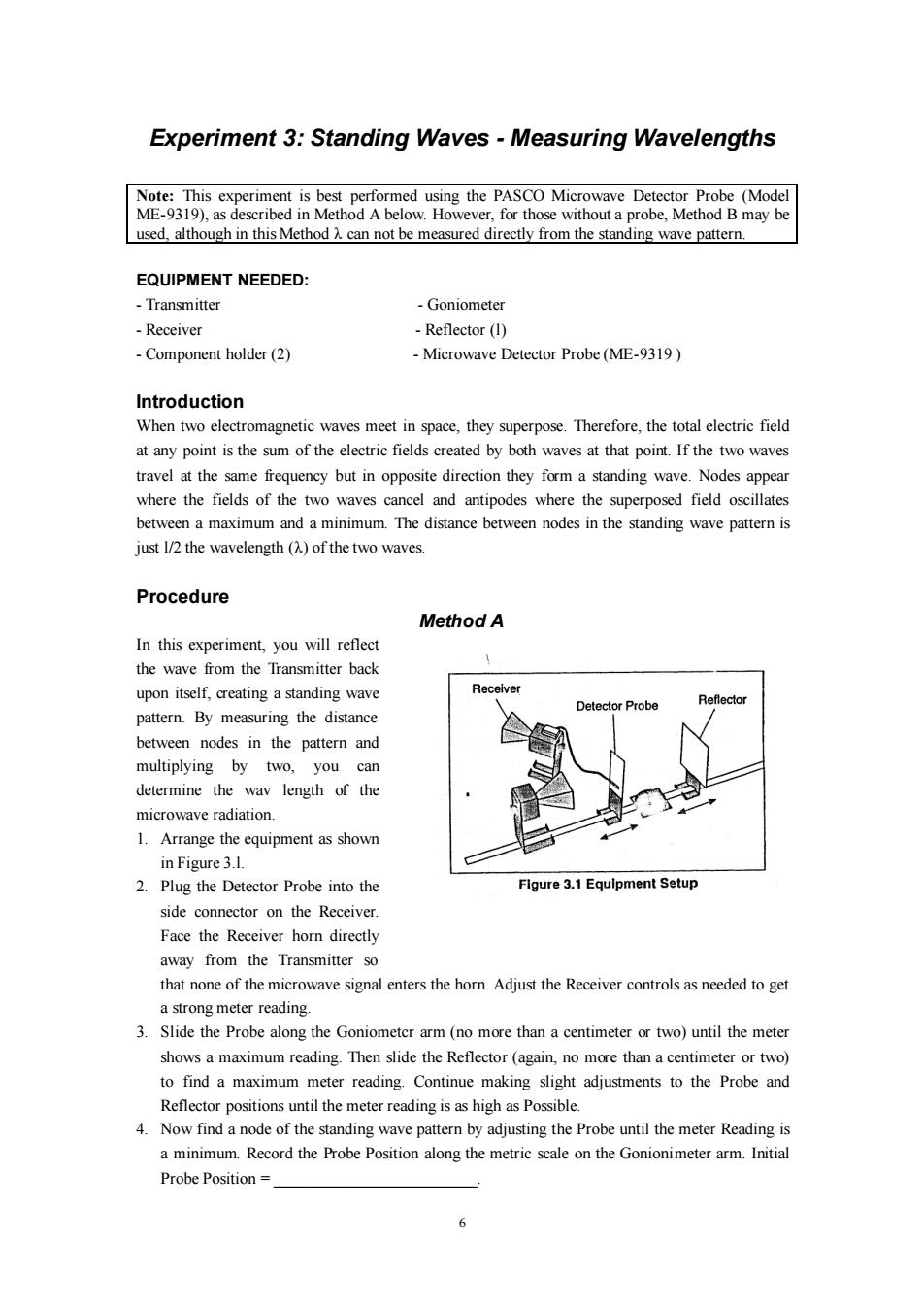
6 Experiment 3: Standing Waves - Measuring Wavelengths Note: This experiment is best performed using the PASCO Microwave Detector Probe (Model ME-9319), as described in Method A below. However, for those without a probe, Method B may be used, although in this Method λ can not be measured directly from the standing wave pattern. EQUIPMENT NEEDED: - Transmitter - Goniometer - Receiver - Reflector (l) - Component holder (2) - Microwave Detector Probe (ME-9319 ) Introduction When two electromagnetic waves meet in space, they superpose. Therefore, the total electric field at any point is the sum of the electric fields created by both waves at that point. If the two waves travel at the same frequency but in opposite direction they form a standing wave. Nodes appear where the fields of the two waves cancel and antipodes where the superposed field oscillates between a maximum and a minimum. The distance between nodes in the standing wave pattern is just l/2 the wavelength (λ) of the two waves. Procedure Method A In this experiment, you will reflect the wave from the Transmitter back upon itself, creating a standing wave pattern. By measuring the distance between nodes in the pattern and multiplying by two, you can determine the wav length of the microwave radiation. 1. Arrange the equipment as shown in Figure 3.l. 2. Plug the Detector Probe into the side connector on the Receiver. Face the Receiver horn directly away from the Transmitter so that none of the microwave signal enters the horn. Adjust the Receiver controls as needed to get a strong meter reading. 3. Slide the Probe along the Goniometcr arm (no more than a centimeter or two) until the meter shows a maximum reading. Then slide the Reflector (again, no more than a centimeter or two) to find a maximum meter reading. Continue making slight adjustments to the Probe and Reflector positions until the meter reading is as high as Possible. 4. Now find a node of the standing wave pattern by adjusting the Probe until the meter Reading is a minimum. Record the Probe Position along the metric scale on the Gonionimeter arm. Initial Probe Position = _________________________
5.While watching the meter,slide the Probe along the Goniometer arm until the Probe has passed through at least 10 antinodes and returned to a node.Record the new position of the Probe and the number of antinodes that were traversed. Antinodes Traversed= Final Probe Position= 6.Use your data to calculate A,the wavelength of the microwave radiation. 九= 7.Repeat your measurements and recalculateA Initial Probe Position Antinodes Traversed Final Probe Position= Questions 1.Use the relationship velocity =u to calculate the frequency of the microwave signal (assuming velocity of propagation in air is 3x10⁸ m/sec). (v=the expected frequency of the microwave radiation-10.525 GHZ). Method B 1.Set up the equipment as shown in Figure 3.2.Adjust the Receiver controls to get a full-scale meter reading with the Transmitter and Receiver as close together as possible.Slowly move the Receiver along the Goniometer arm,away from the Transmitter.How does this motion effect the meter reading?The microwave horns are not perfect collectors of microwave radiation Instead they act as partial reflectors,so that the radiation from the Transmitter reflects back and forth between the Transmitter and Reflector horns,diminishing in amplitude at each pass. λ However,if the distance beteen the Trnsmiter and Receiver diodes is quto(where n is an integer and A is the wavelength of the radiation)then all the multiply-reflected waves entering the Receiver horn will be in phase with the primary transmitted wave.When this occurs,the meter reading will be a maximum.(The distance between adjacent positions in order to see a maximum is therefore-.) 2 >
7 5. While watching the meter, slide the Probe along the Goniometer arm until the Probe has passed through at least 10 antinodes and returned to a node. Record the new position of the Probe and the number of antinodes that were traversed. Antinodes Traversed= _____________________________________. Final Probe Position=_ ____________________________________. 6. Use your data to calculate λ, the wavelength of the microwave radiation. =__________________________________________. 7. Repeat your measurements and recalculate Initial Probe Position = ___________________________. Antinodes Traversed = ________________________________. Final Probe Position = _______________________________. Questions 1. Use the relationship velocity = to calculate the frequency of the microwave signal (assuming velocity of propagation in air is 3 8 10 m/sec). (v = the expected frequency of the microwave radiation -10.525 GHZ). Method B 1. Set up the equipment as shown in Figure 3.2. Adjust the Receiver controls to get a full-scale meter reading with the Transmitter and Receiver as close together as possible. Slowly move the Receiver along the Goniometer arm, away from the Transmitter. How does this motion effect the meter reading? The microwave horns are not perfect collectors of microwave radiation. Instead they act as partial reflectors, so that the radiation from the Transmitter reflects back and forth between the Transmitter and Reflector horns, diminishing in amplitude at each pass. However, if the distance between the Transmitter and Receiver diodes is equal to n 2 , (where n is an integer and λ is the wavelength of the radiation) then all the multiply-reflected waves entering the Receiver horn will be in phase with the primary transmitted wave. When this occurs, the meter reading will be a maximum. (The distance between adjacent positions in order to see a maximum is therefore 2 .)