
OS-9102B Incandescent Light Source OS-9107 Component OS-9106A Angular Translator with component holder OS-9104B Linear Translator 0S-91710.5mW Helium Neon L OS-9172 Laser gnment Bench (wit Optical Component OS-9152B Stude S-8020 High Sensitivity optio probe er-opnc pre 03-9130P1ism OS-9109 Glass Dispersion Tank Incand ce Figure 1:Advanced Optics Equlpment The Optics Bench Optics Light Source component Bench holder The optics bench(see Figure 2)provides a alignment rail straight,rigid surface for aligning optics experiments.For best results,the bench should be placed on a reasonably flat and level surface,and the leveling screws mmmmmmmmmmm should be adjusted so the bench rests leveling screws and locknuts(4) evenly on all four screws.Once the bench metric scale is leveled,tighten the locknuts so there is Figure 2:Using the Optics Bench no slipping. The incandescent light source and the component holders attach magnetically to the bench as shown.For proper alignment,the edge of the light source and component holders should be mounted flush to the alignment rail,which is the raised edge that runs along one side of the bench.This will ensure that the optical axis of the light source and component holders are coincident,which makes it easier to align optical components
4 The Optics Bench The optics bench (see Figure 2) provides a straight, rigid surface for aligning optics experiments. For best results, the bench should be placed on a reasonably flat and level surface, and the leveling screws should be adjusted so the bench rests evenly on all four screws. Once the bench is leveled, tighten the locknuts so there is no slipping. The incandescent light source and the component holders attach magnetically to the bench as shown. For proper alignment, the edge of the light source and component holders should be mounted flush to the alignment rail, which is the raised edge that runs along one side of the bench. This will ensure that the optical axis of the light source and component holders are coincident, which makes it easier to align optical components

Your optics bench is guaranteed straight to within 0.25 mm over its full one meter length,and, under normal use,will retain its straightness.However the optics bench will bow slightly if heavily loaded.For example,a one-kg mass placed in the center of the bench will produce a deflection of approximately 0.07 mm. NOTE:Avoid scratching or otherwise abusing the surface of the magnetic pads on the top of the optics bench.If they get dirty,use only soapy water or rubbing alcohol for cleaning.Other solvents may dissolve the magnetic surfaces. The Incandescent Light Source The incandescent light source(see Figure 3)provides 1 5 candlepower of light with the frequency spectrum shown in Figure4.The built-in power supply of the light source is regulated,so there's minimal variation in the intensity of the light.This is essential for obtaining accurate data in experiments where a photometer is being used to measure light intensities. ·region fuse over the light a ON witch 10 hmmgmmm 1.000 10.000 100,000 filament knob Wavelength in nanometers Flgure 4:Frequency Spectrum for the Figure 3:Using the Incandescent Light Source NOTE:The distance from the front panel of the light source to the light bulb filament is approximately 22 mm. To turn on the light source,connect the power cord to a grounded receptacle of the appropriate line voltage (120 VAC,60 Hz,unless otherwise specified),and flip the switch on the rear panel to ON.If at any time the light fails to come on,chances are that the fuse is blown or the light bulb is burnt out.See the Maintenance section for replacement instructions. The Filament knob on the top of the light source adjusts the position of the light bulb filament transverse to the optical axis of the bench.The filament moves in the same direction as the knob is turned.Components can be mounted onto the magnetic pad on the front panel of the light source, over the light aperture.The crossed-arrow target,for example,is often mounted in this way as an object for lens experiments. CAUTION:When used continuously,the light source becomes hot to the touch.Since it requires no warm-up time,we recommend it be turned on only when setting up or actually performing an experiment
5 Your optics bench is guaranteed straight to within 0.25 mm over its full one meter length, and, under normal use, will retain its straightness. However the optics bench will bow slightly if heavily loaded. For example, a one-kg mass placed in the center of the bench will produce a deflection of approximately 0.07 mm. ★NOTE: Avoid scratching or otherwise abusing the surface of the magnetic pads on the top of the optics bench. If they get dirty, use only soapy water or rubbing alcohol for cleaning. Other solvents may dissolve the magnetic surfaces. The Incandescent Light Source The incandescent light source (see Figure 3) provides 1 5 candlepower of light with the frequency spectrum shown in Figure4. The built-in power supply of the light source is regulated, so there's minimal variation in the intensity of the light. This is essential for obtaining accurate data in experiments where a photometer is being used to measure light intensities. ★NOTE: The distance from the front panel of the light source to the light bulb filament is approximately 22 mm. To turn on the light source, connect the power cord to a grounded receptacle of the appropriate line voltage (120 VAC, 60 Hz, unless otherwise specified), and flip the switch on the rear panel to ON. If at any time the light fails to come on, chances are that the fuse is blown or the light bulb is burnt out. See the Maintenance section for replacement instructions. The Filament knob on the top of the light source adjusts the position of the light bulb filament transverse to the optical axis of the bench. The filament moves in the same direction as the knob is turned. Components can be mounted onto the magnetic pad on the front panel of the light source, over the light aperture. The crossed-arrow target, for example, is often mounted in this way as an object for lens experiments. ★CAUTION: When used continuously, the light source becomes hot to the touch. Since it requires no warm-up time, we recommend it be turned on only when setting up or actually performing an experiment
Specifications for the incandescent Light Source(Model OS-9102B) Output:Approximately 15 candlepower Filament temperature:2700K Bulb:#93,operated at 12 VDC,1.0 A;bulb life approximately 700 hours Regulation:Maximum intensity variation of 2%for a 10%change in line voltage. Input Power:105-125 VAC 60 Hz (or 210-240 VAC,50 Hz if specified when ordered) Fuse 0.5A,Slo-Blo (0.25 A for 220 VAC model) The Helium Neon Laser The helium neon laser is a 0.5 mW,TEMoo mode laser,providing randomly polarized light at a wavelength of 632.8 nm.The built-in power supply is regulated so the output has minimum ripple and the intensity is stable to within +2.5%.A 15 minute warm up is required to reach full power, but the power on start-up is greater than 0.35 mW.If you'd like more technical specifications,and a detailed explanation of laser operation,see the instruction manual that's included with the laser. *COUTION:This is a relatively safe,low power laser.Nevertheless,we strongly recommend the following precautions: Never look into the laser beam,either directly,or as it is reflected from a mirror. Set up experiments so the laser is either above or below eye level(for both sitting and standing people). To Setup the Laser using the Laser Alignment Bench: The laser is most conveniently aligned using the laser alignment bench,which can be joined to the optics bench using the bench couplers.The procedure is as follows: 1Place the optics bench and the laser alignment bench end to end,as in Figure5.Notice that only one end of the laser alignment bench has holes for two leveling screws.That is the end that joins to the optics bench. lase bench coupler Laser Alignment Bench 14-20hex ead scrov leveling screw and lock-nut bench coupler Laser Alignment Bench 1111111111171hT Top View of Bench Coupler bench couple Optics Bench Figure 5:Connecting the Laser Alignment Bench 2Remove the four leveling screws on the adjoining ends of the two benches. 6
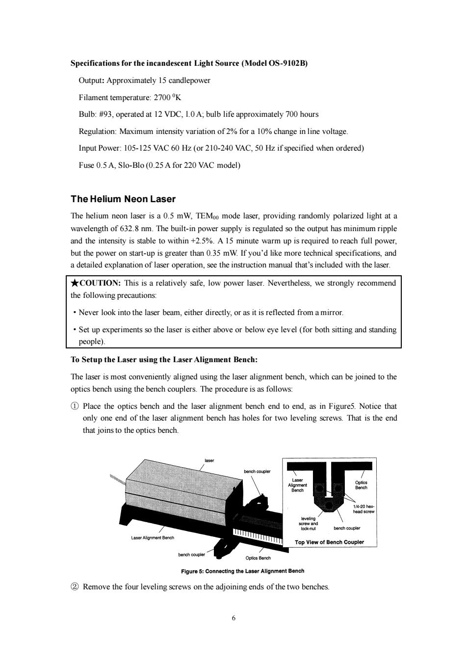
6 Specifications for the incandescent Light Source (Model OS-9102B) Output: Approximately 15 candlepower Filament temperature: 2700 0K Bulb: #93, operated at 12 VDC, l.0 A; bulb life approximately 700 hours Regulation: Maximum intensity variation of 2% for a 10% change in line voltage. Input Power: 105-125 VAC 60 Hz (or 210-240 VAC, 50 Hz if specified when ordered) Fuse 0.5 A, Slo-Blo (0.25 A for 220 VAC model) The Helium Neon Laser The helium neon laser is a 0.5 mW, TEM00 mode laser, providing randomly polarized light at a wavelength of 632.8 nm. The built-in power supply is regulated so the output has minimum ripple and the intensity is stable to within +2.5%. A 15 minute warm up is required to reach full power, but the power on start-up is greater than 0.35 mW. If you’d like more technical specifications, and a detailed explanation of laser operation, see the instruction manual that’s included with the laser. ★COUTION: This is a relatively safe, low power laser. Nevertheless, we strongly recommend the following precautions: ·Never look into the laser beam, either directly, or as it is reflected from a mirror. ·Set up experiments so the laser is either above or below eye level (for both sitting and standing people). To Setup the Laser using the Laser Alignment Bench: The laser is most conveniently aligned using the laser alignment bench, which can be joined to the optics bench using the bench couplers. The procedure is as follows: ① Place the optics bench and the laser alignment bench end to end, as in Figure5. Notice that only one end of the laser alignment bench has holes for two leveling screws. That is the end that joins to the optics bench. ② Remove the four leveling screws on the adjoining ends of the two benches

3 Use the 1/4-20,hex-head screws that are included with the bench couplers to attach the couplers to the legs of the benches,as shown.Do not yet tighten the screws. 4 Insert one of the leveling screws,rubber foot down,through the threaded hole in each coupler. 5 By adjusting all five leveling screws(one on the laser alignment bench,two on the optics bench,and two on the bench couplers),align the two benches so they are in a straight line.Use a meter stick or a long straight edge on top of the benches to check vertical alignment,and on the side of the bench to check horizontal alignment. 6When the benches are aligned,tighten the locknuts on all the leveling screws,and also tighten the four hex-head screws.After tightening the screws,recheck the alignment. To Align the Laser(so the laser beam is coincident with the optical axis of the bench): 1Place a piece of masking tape or tape a piece of paper over the square hole on the front of a component holder,as in Figure 6.Make a small dot on the tape or paper,in the center of the square hole (1-inch from the top of the component shelf and 1.5-inch from the edge of the component holder). dot 2Place the laser on the alignment bench,as in Figure 5.Center the laser on the bench,and make sure it is reasonably parallel with the bench. 3Place the component holder on the optics bench,about 10 cm from the laser aperture.Make sure that the component holder is flush against the alignment rail of the bench.The dot on the tape now marks the optical axis of the bench. 4 Turn on the laser,and move the aperture end of the laser Flgure 6:Locating sideways,as needed,so that the laser beam falls on the dot. the Optical Axis 5Move the component holder about 90 cm away from the laser aperture.Again,be sure the edge of the component holder is flush against the alignment rail of the bench. 6Without moving the aperture end of the laser,move the rear end of the laser as needed to recent the laser beam on the dot.(You may also need to adjust the leveling screws on the laser alignment bench in order to center the laser beam vertically on the dot.) 7 Repeat steps 3 through 6 until the laser beam is aligned with the dot for both positions of the component holder. The Component Holders Each optics system includes several of the standard component holders that attach magnetically to the optics bench,as in Figure 7.Components mount magnetically onto either side of the component holders.For proper alignment of the components along the optical axis of the bench: DMount the component holder flush against the alignment rail of the bench,as in Figure 7. >
7 ③ Use the 1/4-20, hex-head screws that are included with the bench couplers to attach the couplers to the legs of the benches, as shown. Do not yet tighten the screws. ④ Insert one of the leveling screws, rubber foot down, through the threaded hole in each coupler. ⑤ By adjusting all five leveling screws (one on the laser alignment bench, two on the optics bench, and two on the bench couplers), align the two benches so they are in a straight line. Use a meter stick or a long straight edge on top of the benches to check vertical alignment, and on the side of the bench to check horizontal alignment. ⑥ When the benches are aligned, tighten the locknuts on all the leveling screws, and also tighten the four hex-head screws. After tightening the screws, recheck the alignment. To Align the Laser (so the laser beam is coincident with the optical axis of the bench): ① Place a piece of masking tape or tape a piece of paper over the square hole on the front of a component holder, as in Figure 6. Make a small dot on the tape or paper, in the center of the square hole (1-inch from the top of the component shelf and 1.5-inch from the edge of the component holder). ② Place the laser on the alignment bench, as in Figure 5. Center the laser on the bench, and make sure it is reasonably parallel with the bench. ③ Place the component holder on the optics bench, about 10 cm from the laser aperture. Make sure that the component holder is flush against the alignment rail of the bench. The dot on the tape now marks the optical axis of the bench. ④ Turn on the laser, and move the aperture end of the laser sideways, as needed, so that the laser beam falls on the dot. ⑤ Move the component holder about 90 cm away from the laser aperture. Again, be sure the edge of the component holder is flush against the alignment rail of the bench. ⑥ Without moving the aperture end of the laser, move the rear end of the laser as needed to recent the laser beam on the dot. (You may also need to adjust the leveling screws on the laser alignment bench in order to center the laser beam vertically on the dot.) ⑦ Repeat steps 3 through 6 until the laser beam is aligned with the dot for both positions of the component holder. The Component Holders Each optics system includes several of the standard component holders that attach magnetically to the optics bench, as in Figure 7. Components mount magnetically onto either side of the component holders. For proper alignment of the components along the optical axis of the bench: ①Mount the component holder flush against the alignment rail of the bench, as in Figure 7
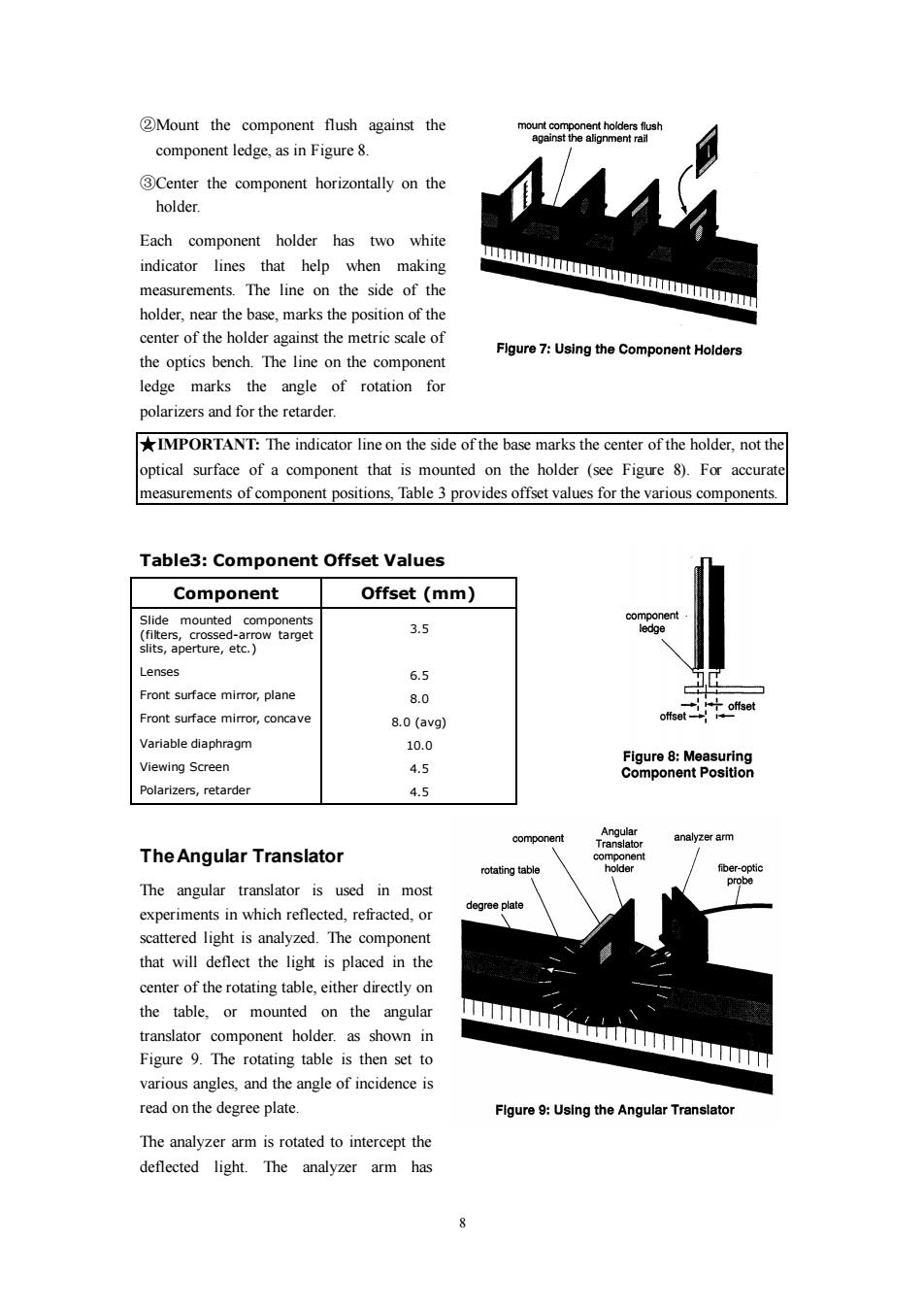
2Mount the component flush against the mount component holders flush against the alignment rail component ledge,as in Figure 8. 3Center the component horizontally on the holder. Each component holder has two white indicator lines that help when making measurements.The line on the side of the mmm holder,near the base,marks the position of the center of the holder against the metric scale of Figure 7:Using the Component Holders the optics bench.The line on the component ledge marks the angle of rotation for polarizers and for the retarder. IMPORTANT:The indicator line on the side of the base marks the center of the holder,not the optical surface of a component that is mounted on the holder (see Figure 8).For accurate measurements of component positions,Table 3 provides offset values for the various components. Table3:Component Offset Values Component Offset(mm) Slide mounted components component (filters,crossed-arrow target 3.5 ledge slits,aperture,etc. Lenses 6.5 Front surface mirror,plane 8.0 offset offset Front surface mirror,concave 8.0(avg) Variable diaphragm 10.0 Figure 8:Measuring Viewing Screen 4.5 Component Position Polarizers,retarder 4.5 Angular component analyzer arm Translator The Angular Translator component rotating table holder f他er-optic The angular translator is used in most probe experiments in which reflected,refracted,or degree plate scattered light is analyzed.The component that will deflect the light is placed in the center of the rotating table,either directly on the table,or mounted on the angular translator component holder.as shown in Figure 9.The rotating table is then set to various angles,and the angle of incidence is read on the degree plate. Flgure 9:Using the Angular Translator The analyzer arm is rotated to intercept the deflected light.The analyzer arm has 8
8 ②Mount the component flush against the component ledge, as in Figure 8. ③Center the component horizontally on the holder. Each component holder has two white indicator lines that help when making measurements. The line on the side of the holder, near the base, marks the position of the center of the holder against the metric scale of the optics bench. The line on the component ledge marks the angle of rotation for polarizers and for the retarder. ★IMPORTANT: The indicator line on the side of the base marks the center of the holder, not the optical surface of a component that is mounted on the holder (see Figure 8). For accurate measurements of component positions, Table 3 provides offset values for the various components. Table3: Component Offset Values Component Offset (mm) Slide mounted components (filters, crossed-arrow target slits, aperture, etc.) Lenses Front surface mirror, plane Front surface mirror, concave Variable diaphragm Viewing Screen Polarizers, retarder 3.5 6.5 8.0 8.0 (avg) 10.0 4.5 4.5 The Angular Translator The angular translator is used in most experiments in which reflected, refracted, or scattered light is analyzed. The component that will deflect the light is placed in the center of the rotating table, either directly on the table, or mounted on the angular translator component holder. as shown in Figure 9. The rotating table is then set to various angles, and the angle of incidence is read on the degree plate. The analyzer arm is rotated to intercept the deflected light. The analyzer arm has