
Chapter 7 Spread Spectrum Communication Systems 7.1 Preview Spread spectrum signals for digital communications were spectrum:频谱 originally developed and used for military communications either hostile:敌对的 (1)to provide resistance to hostile jamming;(2)to hide the signal jamming:人为干扰 by transmitting it at low power,thus making it difficult for an unintended:无意识的 unintended listener to detect its presence in noise;or(3)to make wireless:无线的 it possible for multiple users to communicate through the same illustrated:有插图的 channel.Today,however,spread spectrum signals are being used pseudorandom:伪随机的 to provide reliable communications in a variety of commercial sequence:序列 applications,including mobile vehicular communications and generator:发生器 interoffice wireless communications. identical:同样的 The basic elements of a spread spectrum digital pseudonoise:伪噪声 communication system are illustrated in Figure7.1.We observe binary-valued:二值序列 that the channel encoder and decoder and the modulator and despread:扩展 demodulator are the basic elements of a conventional digital demodulator:解调器 communication system.In addition to these elements,a spread spectrum system employs identical pseudorandom sequence generators,one of which interfaces with the modulator at the transmitting end and the second of which interfaces with the demodulator at the receiving end.These two generators produce a pseudorandom or pseudonoise (PN)binary-valued sequence that is used to spread the transmitted signal in frequency at the modulator and to despread the received signal at the demodulator. Pseudorandom Pattern generator Information sequence Channel Modulator encoder Channel Noise Demodulator Output Channel Pseudorandom data decoder Pattern generator Figure 7.1 Model of spread spectrum digital communication system
Chapter 7 Spread Spectrum Communication Systems 7.1 Preview Spread spectrum signals for digital communications were originally developed and used for military communications either (1) to provide resistance to hostile jamming; (2) to hide the signal by transmitting it at low power, thus making it difficult for an unintended listener to detect its presence in noise; or (3) to make it possible for multiple users to communicate through the same channel. Today, however, spread spectrum signals are being used to provide reliable communications in a variety of commercial applications, including mobile vehicular communications and interoffice wireless communications. The basic elements of a spread spectrum digital communication system are illustrated in Figure7.1. We observe that the channel encoder and decoder and the modulator and demodulator are the basic elements of a conventional digital communication system. In addition to these elements, a spread spectrum system employs identical pseudorandom sequence generators, one of which interfaces with the modulator at the transmitting end and the second of which interfaces with the demodulator at the receiving end. These two generators produce a pseudorandom or pseudonoise (PN) binary-valued sequence that is used to spread the transmitted signal in frequency at the modulator and to despread the received signal at the demodulator. Channel encoder Channel Modulator Noise Demodulator Channel decoder Pseudorandom Pattern generator Pseudorandom Pattern generator Information sequence Output data Figure 7.1 Model of spread spectrum digital communication system spectrum:频谱 hostile:敌对的 jamming:人为干扰 unintended:无意识的 wireless:无线的 illustrated:有插图的 pseudorandom:伪随机的 sequence:序列 generator:发生器 identical:同样的 pseudonoise:伪噪声 binary-valued:二值序列 despread:扩展 demodulator:解调器

Time synchronization of the PN sequence generated at the spectrum:频谱 receiver with the PN sequence contained in the receiver signal is hostile:敌对的 required to properly despread the received spread spectrum jamming:人为千扰 signal.In a practical system,synchronization is established prior unintended:无意识的 to the transmission of information by transmitting a fixed PN bit wireless:.无线的 pattern that is designed so that the receiver will detect it with llustrated:有插图的 high probability in the presence of interference.After time pseudorandom:伪随机的 synchronization of the PN sequence generator is established,the sequence:序列 transmission of information commences.In the data mode,the generator:发生器 communications system usually tracks the timing of the identical:同样的 incoming received signal and keeps the PN sequence generator in pseudonoise:伪噪声 synchronism. binary-valued:二值序列 In this chapter,we consider one basic types of spread spectrum despread:扩展 signals for digital communications-namely,direct-sequence demodulator:解调器 (DS)spread spectrum. Two types of digital modulation are considered in conjunction with spread spectrum-namely,PSK and FSK,PSK modulation is generally used with DS spread spectrum and is appropriate for applications where phase coherence between the transmitted signal and the received signal can be maintained over a time interval that spans several symbol (or bit)intervals.On the other hand,FSK modulation is commonly used with FH spread spectrum and is appropriate in applications where phase coherence of the carrier cannot be maintained due to time variations in the transmission characteristics of the communications channel. 7.2 Direct-Sequence Spread Spectrum System Let us consider the transmission of a binary information sequence by means of binary PSK.The information rate is R bit per second,and the bit interval is T=1/R seconds.The available channel bandwidth is Be hertz,where Be>>R.At the modulator, the bandwidth of the information signal is expanded to W=Be hertz by shifting the phase of the carrier pseudorandomly at a rate of W times per second according to the pattern of the PN generator.The resulting modulated signal is called a direct-sequence(DS)spread spectrum signal. The information-bearing baseband signal is denoted as v and is expressed as 0=2a,8,-n7) (7.2.10 Where fan=+1,-n+and gr(t)is a rectangular pulse of duration T.This signal is multiplied by the signal from the PN
Time synchronization of the PN sequence generated at the receiver with the PN sequence contained in the receiver signal is required to properly despread the received spread spectrum signal. In a practical system, synchronization is established prior to the transmission of information by transmitting a fixed PN bit pattern that is designed so that the receiver will detect it with high probability in the presence of interference. After time synchronization of the PN sequence generator is established, the transmission of information commences. In the data mode, the communications system usually tracks the timing of the incoming received signal and keeps the PN sequence generator in synchronism. In this chapter, we consider one basic types of spread spectrum signals for digital communications—namely, direct-sequence (DS) spread spectrum. Two types of digital modulation are considered in conjunction with spread spectrum—namely, PSK and FSK, PSK modulation is generally used with DS spread spectrum and is appropriate for applications where phase coherence between the transmitted signal and the received signal can be maintained over a time interval that spans several symbol (or bit) intervals. On the other hand, FSK modulation is commonly used with FH spread spectrum and is appropriate in applications where phase coherence of the carrier cannot be maintained due to time variations in the transmission characteristics of the communications channel. 7.2 Direct-Sequence Spread Spectrum System Let us consider the transmission of a binary information sequence by means of binary PSK. The information rate is R bit per second, and the bit interval is Tb=1/R seconds. The available channel bandwidth is Bc hertz, where Bc>> R. At the modulator, the bandwidth of the information signal is expanded to W= Bc hertz by shifting the phase of the carrier pseudorandomly at a rate of W times per second according to the pattern of the PN generator. The resulting modulated signal is called a direct-sequence (DS) spread spectrum signal. The information-bearing baseband signal is denoted as v(t) and is expressed as ( ) ( ) n T b n v t a g t nT = = − (7.2.1) Where {an=±1, -∞<n<+∞}and gT(t) is a rectangular pulse of duration Tb. This signal is multiplied by the signal from the PN spectrum:频谱 hostile:敌对的 jamming:人为干扰 unintended:无意识的 wireless:无线的 illustrated:有插图的 pseudorandom:伪随机的 sequence:序列 generator:发生器 identical:同样的 pseudonoise:伪噪声 binary-valued:二值序列 despread:扩展 demodulator:解调器
sequence generator,which may be expressed as multiply:乘法 dt)=Ec.p(t-nT.) approximately:大约 (7.2.2) spectra:频谱 convolution:卷积 Where fcn represents the binary PN code sequence of +l's and amplitude-modulate: p is a rectangular pulse of duration Te,as illustrated in Figure 度调制 7.2.This multiplication operation serves to spread the bandwidth carrier:载波 of the information-bearing signal (whose bandwidth is carrier-modulate:载波调 approximately R hertz)into the wider bandwidth occupied by PN 制 generator signal c(t)(whose bandwidth is approximately 1/T) phase:相位 The spectrum spreading is illustrated in Figure 7.3,which shows, in simple terms using rectangular spectra,the convolution of the two spectra,the narrow spectrum corresponding to the information-bearing signal and wide spectrum corresponding to the signal from the PN generator. The produce signal vct),also illustrated in Figure 7.2,is used to amplitude-modulate the carrier A cos2zf and,thus,to generate the DSB-SC signal u(1)=Av(t)c(t)cos2zft (7.2.3) Since v(c)=I for any t,it follows that the carrier-modulated transmitted signal may also be expressed as u(t)=A.cos[2πf1+θt)] (7.2.4) Where 0t)=0 when v(t)c(()=1 and et)=1 when v(t)c(()=-1. Therefore the transmitted signal is a binary PSK signal whose phase varies at the rate 1/Tc. (a】 v(t) (b) c(t)v(t) (c) Figure 7.2 Generation of a DS spread spectrum signal (a)PN signal;(b)data signal;(c)product signal The rectangular pulse p is usually called a chip,and its time duration,Te,is called the chip interval.The reciprocal 1/Te is called the chip rate and corresponds (approximately)to the
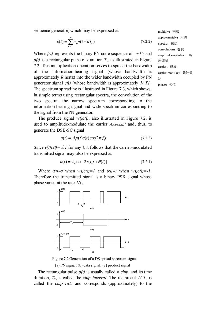
sequence generator, which may be expressed as ( ) ( ) n c n c t c p t nT = = − (7.2.2) Where {cn} represents the binary PN code sequence of ±1’s and p(t) is a rectangular pulse of duration Tc, as illustrated in Figure 7.2. This multiplication operation serves to spread the bandwidth of the information-bearing signal (whose bandwidth is approximately R hertz) into the wider bandwidth occupied by PN generator signal c(t) (whose bandwidth is approximately 1/ Tc). The spectrum spreading is illustrated in Figure 7.3, which shows, in simple terms using rectangular spectra, the convolution of the two spectra, the narrow spectrum corresponding to the information-bearing signal and wide spectrum corresponding to the signal from the PN generator. The produce signal v(t)c(t), also illustrated in Figure 7.2, is used to amplitude-modulate the carrier Accos2πfct and, thus, to generate the DSB-SC signal ( ) ( ) ( )cos2 c c u t A v t c t f t = (7.2.3) Since v(t)c(t)=±1 for any t, it follows that the carrier-modulated transmitted signal may also be expressed as ( ) cos[2 ( )] c c u t A f t t = + (7.2.4) Where (t)=0 when v(t)c(t)=1 and (t)=1 when v(t)c(t)=-1. Therefore the transmitted signal is a binary PSK signal whose phase varies at the rate 1/Tc. 1 -1 1 -1 1 -1 t t t c(t) v(t) c(t)v(t) Tc Tb Tb (a) (b) (c) Figure 7.2 Generation of a DS spread spectrum signal (a) PN signal; (b) data signal; (c) product signal The rectangular pulse p(t) is usually called a chip, and its time duration, Tc, is called the chip interval. The reciprocal 1/ Tc is called the chip rate and corresponds (approximately) to the multiply:乘法 approximately:大约 spectra:频谱 convolution:卷积 amplitude-modulate: 幅 度调制 carrier:载波 carrier-modulate:载波调 制 phase:相位

band width W of the transmitted signal.The ratio of the bit rectangular pulse:矩形 interval Toto the chip interval Te is usually selected to be an 脉冲 integer in practical spread spectrum systems.We denote this ratio as chip:码片 interval::间隔 L.= (7.2.5) reciprocal:倒数 integer:整数 Hence,Lc is the number of chips of the PN code sequence per denote:表示 information bit.Another interpretation is that Le represents the number of possible 180 phase transitions in the transmitted demodulation:解调 signal during the interval To. replica:副本 ◆V(f waveform:波形 dispreading:解扩 f -1T601/Tb (a) 个C() →f -1/Tc 0 I/T (b) 个V(*C() -(1/T+1/T6) 0 1/T+ITb (c) Figure 7.3 Convolution of spectra of the (a)data signal with the(b)PN code signal 7.2.1 Signal Demodulation The demodulation of the signal is performed as illustrated in Figure 7.4.The received signal is first multiplied by a replica of the waveform ct)generated by the PN code sequence generator at the receiver,which is synchronized to the PN code in the received signal.This operator is called(spectrum)despreading, since the effect of multiplication by ct)at the receiver is to undo the spreading operation at the transmitter.Thus,we have Av(t)c2(t)cos2πft=A.v(t)cos2πft (7.2.6 since c2t)=I for all t.The resulting signal Aev(t)cos2zfet occupies a bandwidth(approximately)of R hertz,which is the bandwidth of the information-bearing signal.Therefore,the demodulator for the despread signal is simply the conventional cross-correlator or matched filter that was described in Chapter 5 and 7.Since the
bandwidth W of the transmitted signal. The ratio of the bit interval Tb to the chip interval Tc is usually selected to be an integer in practical spread spectrum systems. We denote this ratio as b c c T L T = (7.2.5) Hence, Lc is the number of chips of the PN code sequence per information bit. Another interpretation is that Lc represents the number of possible 180o phase transitions in the transmitted signal during the interval Tb. (c) (b) (a) f f f V(f) C(f) V(f)*C(f) -1/Tb 0 1/Tb -1/Tc 0 1/Tc -(1/Tc+1/Tb) 0 1/Tc+1/Tb Figure 7.3 Convolution of spectra of the (a) data signal with the (b) PN code signal 7.2.1 Signal Demodulation The demodulation of the signal is performed as illustrated in Figure 7.4. The received signal is first multiplied by a replica of the waveform c(t) generated by the PN code sequence generator at the receiver, which is synchronized to the PN code in the received signal. This operator is called (spectrum) despreading, since the effect of multiplication by c(t) at the receiver is to undo the spreading operation at the transmitter. Thus, we have 2 ( ) ( )cos 2 ( )cos 2 A v t c t f t A v t f t c c c c = (7.2.6) since c 2 (t)=1 for all t. The resulting signal Acv(t)cos2πfct occupies a bandwidth (approximately) of R hertz, which is the bandwidth of the information-bearing signal. Therefore, the demodulator for the despread signal is simply the conventional cross-correlator or matched filter that was described in Chapter 5 and 7. Since the rectangular pulse:矩形 脉冲 chip:码片 interval:间隔 reciprocal:倒数 integer:整数 denote:表示 demodulation:解调 replica:副本 waveform:波形 dispreading:解扩

demodulator has a bandwidth that is identical to the bandwidth of despread:解扩 the despread signal,the only additive noise that corrupts the cross-correlator:互相关 signal at the demodulator is the noise that falls within the 0 information bandwidth of the received signal. matched filter:匹配滤波 器 PN signal additive noise:加性噪声 generator 8r(t)cos2πf1 corrupts:污损 Narrowband:窄带 Received sinusoidal:正弦 Signal r(t) (h To decoder Sampler Clock signal Figure 7.4 Demodulation of DS spread spectrum signal Effects of Despreading on Narrowband Interference It is interesting to investigate the effect of an interfering signal on the demodulator of the desired information-bearing signal. Suppose that the received signal is r(t)=A.v(t)c(t)cos2nft+i(t) (7.2.7) where it)denotes the interference.The dispreading operation at the receiver yields r(t)c(1)=Av(t)c(t)cos2nft+i(t)c(t) (7.2.8) The effect of multiplying the interference it)with c is so spread the band width of ift)to W hertz. As an example,let us consider a sinusoidal interfering signal of the form i(t)=Acos2πfj1 (7.2.9) where f is a frequency within the bandwidth of the transmitted signal,Its multiplication with ct)results in a wideband interference with power-spectral density Jo=P//W,where PJ=A21/2 is the average power of the interference.Since the
demodulator has a bandwidth that is identical to the bandwidth of the despread signal, the only additive noise that corrupts the signal at the demodulator is the noise that falls within the information bandwidth of the received signal. Sampler PN signal generator Received Signal r(t) ( )cos 2 T c g t f t Clock signal To decoder ( ) 0 Ts dt Figure 7.4 Demodulation of DS spread spectrum signal Effects of Despreading on Narrowband Interference It is interesting to investigate the effect of an interfering signal on the demodulator of the desired information-bearing signal. Suppose that the received signal is ( ) ( ) ( )cos 2 ( ) c c r t A v t c t f t i t = + (7.2.7) where i(t) denotes the interference. The dispreading operation at the receiver yields ( ) ( ) ( ) ( )cos2 ( ) ( ) c c r t c t A v t c t f t i t c t = + (7.2.8) The effect of multiplying the interference i(t) with c(t) is so spread the bandwidth of i(t) to W hertz. As an example, let us consider a sinusoidal interfering signal of the form ( ) cos 2 J J i t A f t = (7.2.9) where fJ is a frequency within the bandwidth of the transmitted signal, Its multiplication with c(t) results in a wideband interference with power-spectral density J0=PJ/W, where PJ=A2 J/2 is the average power of the interference. Since the despread:解扩 cross-correlator:互相关 器 matched filter:匹配滤波 器 additive noise:加性噪声 corrupts:污损 Narrowband:窄带 sinusoidal:正弦