Effect of high current Large voltage drop on bonding wire Example:0->4A at 1 GHz if the voltage drop across this inductance must remain below 100 mV? Ls<7.96pH. This is an extremely small inductance.(A single bond wire's inductance typically exceeds 1 nH
Effect of high current Large voltage drop on bonding wire ◦ Example: 0->4A at 1 GHz ◦ if the voltage drop across this inductance must remain below 100 mV? This is an extremely small inductance. (A single bond wire’s inductance typically exceeds 1 nH.)
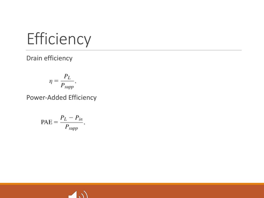
Efficiency Drain efficiency PL 升= Psupp Power-Added Efficiency PAE=PL -P'm Psupp
Efficiency Drain efficiency Power-Added Efficiency
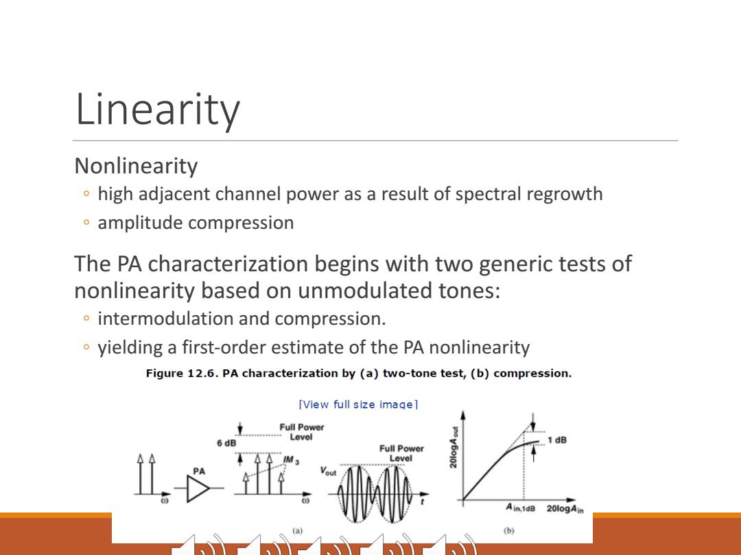
Linearity Nonlinearity high adjacent channel power as a result of spectral regrowth amplitude compression The PA characterization begins with two generic tests of nonlinearity based on unmodulated tones: intermodulation and compression. yielding a first-order estimate of the PA nonlinearity Figure 12.6.PA characterization by (a)two-tone test,(b)compression. [View full size imagel Full Power Level Full Power Level Ain,1dB 20logAin (b)
Linearity Nonlinearity ◦ high adjacent channel power as a result of spectral regrowth ◦ amplitude compression The PA characterization begins with two generic tests of nonlinearity based on unmodulated tones: ◦ intermodulation and compression. ◦ yielding a first-order estimate of the PA nonlinearity
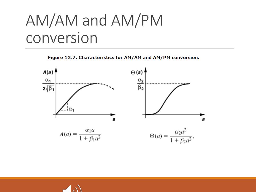
AM/AM and AM/PM conversion Figure 12.7.Characteristics for AM/AM and AM/PM conversion. A(a) 日(a) 2师 影 01 a a aja A(a)= 2a2 1+B1a2 ⊙(@)= 1+2a21
AM/AM and AM/PM conversion

Single-Ended and Differential PAS Most stand-alone PAs have been designed as a cascade of single-ended stages.Two reasons account for this choice: the antenna is typically single-ended, and single-ended RF circuits are much simpler to test than their differential counterparts. Drawbacks First,they "waste"half of the transmitter voltage gain Large current induced feedback
Single-Ended and Differential PAs Most stand-alone PAs have been designed as a cascade of single-ended stages. Two reasons account for this choice: ◦ the antenna is typically single-ended, ◦ and single-ended RF circuits are much simpler to test than their differential counterparts. Drawbacks ◦ First, they “waste” half of the transmitter voltage gain ◦ Large current induced feedback