Continue Carnot Power Cycle Example 39.1: Given:TH 500 K and T 300 K Find:Thermal efficiency of Carnot Cycle Solution:nth.c=0.4 1.0 b Question: How to implement the 0.5 Carnot Power Cycle 0 a with a real working fluid? L 298100020003000 TH(K) 上游究通大学 Wednesday,April 26,2017 6 SHANGHAI JLAO TONG UNIVERSITY
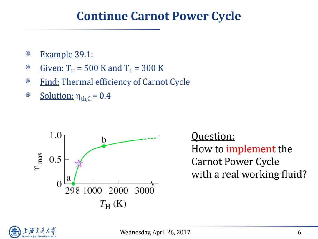
Wednesday, April 26, 2017 6 Continue Carnot Power Cycle Example 39.1: Given: TH = 500 K and TL = 300 K Find: Thermal efficiency of Carnot Cycle Solution: th,C = 0.4 Question: How to implement the Carnot Power Cycle with a real working fluid?
Continue Carnot power cycle Answer: Put the cycle under the two-phase dome TH S1=S2 S3=S4 However,in real world we have to "deal"with deviations from Carnot: finite temperature difference across the heat exchange difficult to compress 2-phase mixture non-isentropic compression and expansion >Introduce Rankine power cycle 上游充通大 Wednesday,April 26,2017 7 SHANGHAI JIAO TONG UNIVERSITY
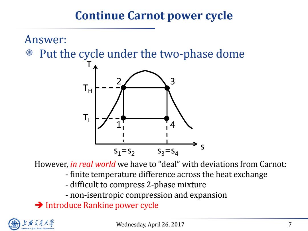
Wednesday, April 26, 2017 7 Continue Carnot power cycle Answer: Put the cycle under the two-phase dome However, in real world we have to “deal” with deviations from Carnot: - finite temperature difference across the heat exchange - difficult to compress 2-phase mixture - non-isentropic compression and expansion Introduce Rankine power cycle T s 1 2 3 4 s1=s2 s3=s4 TH TL
Ideal Rankine Power Cycle System Schematic and T-s diagram: qin 3 Boiler T Wturb.out Turbine Wpump.in Wturb.out Pump qin 2 3 Condenser 2 qout pump.in 上游充通大 Wednesday,April 26,2017 8 SHANGHAI JIAO TONG UNIVERSITY
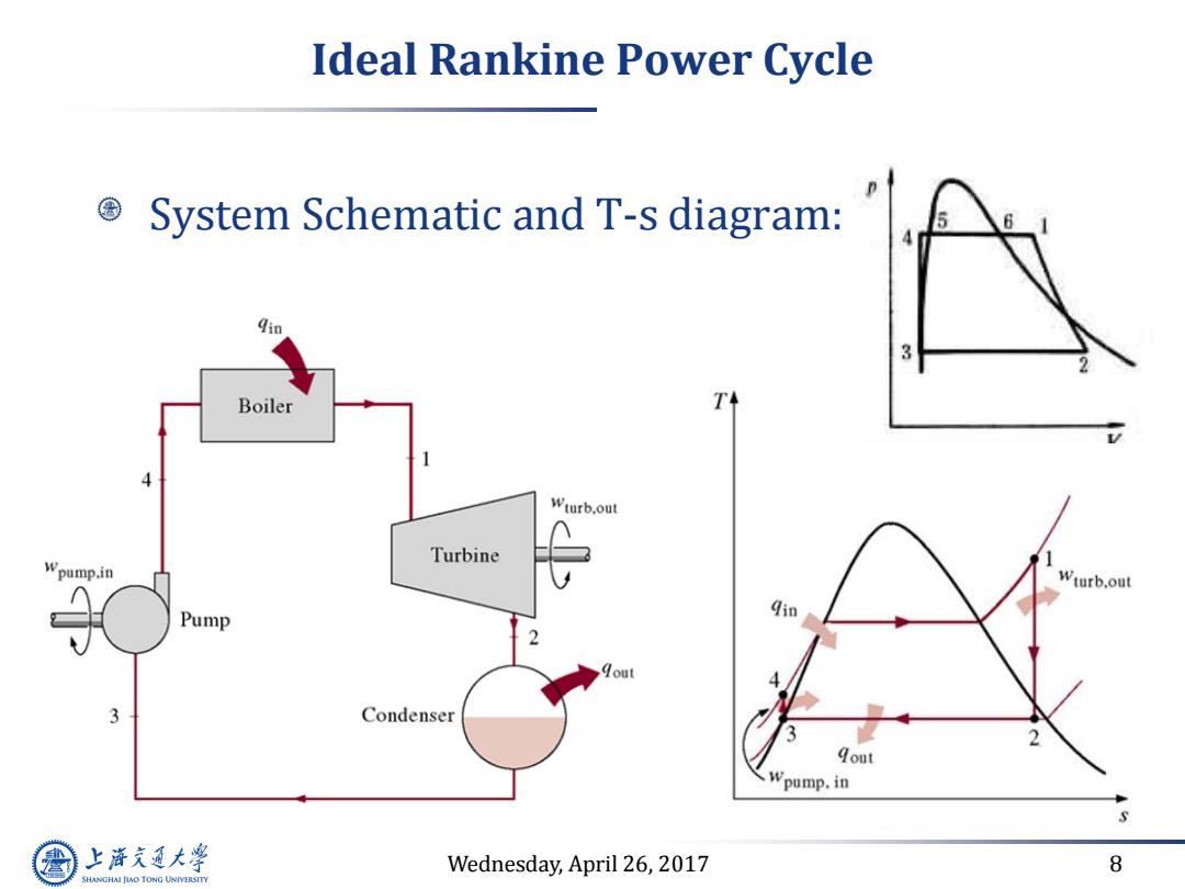
Wednesday, April 26, 2017 8 Ideal Rankine Power Cycle System Schematic and T-s diagram:
Continue Ideal Rankine Power Cycle Define ideal Rankine power cycle: .Neglect the finite temperature difference of heat exchanger →△THx=0,TBoiler=TH and Tcond=TL Isentropic expansion and pumping processes →S1=S2andS3=s4 Difference between ideal Rankine and Carnot power cycle: ·①Instead of isentropic compression from3→4(Carnot),itis isentropic pumping from saturated liquid (3)to subcooled liquid (4)(Rankine)due to the use of actual working fluid (water/steam) ·②Quality at turbine exit not too low> Cooling curve for the products of combustion 3Rankine:Non-isothermal heat addition,good the combustion heat ·④Carnot:two-phase pump is hard to handle 上游通大学 Wednesday,April 26,2017 9 SHANGHAI JIAO TONG UNIVERSITY
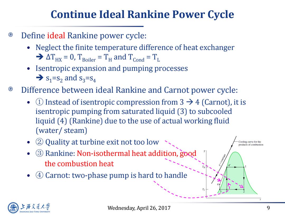
Wednesday, April 26, 2017 9 Continue Ideal Rankine Power Cycle Define ideal Rankine power cycle: • Neglect the finite temperature difference of heat exchanger ∆THX = 0, TBoiler = TH and TCond = TL • Isentropic expansion and pumping processes s1=s2 and s3=s4 Difference between ideal Rankine and Carnot power cycle: • ① Instead of isentropic compression from 3 4 (Carnot), it is isentropic pumping from saturated liquid (3) to subcooled liquid (4) (Rankine) due to the use of actual working fluid (water/ steam) • ② Quality at turbine exit not too low • ③ Rankine: Non-isothermal heat addition, good for using the combustion heat • ④ Carnot: two-phase pump is hard to handle
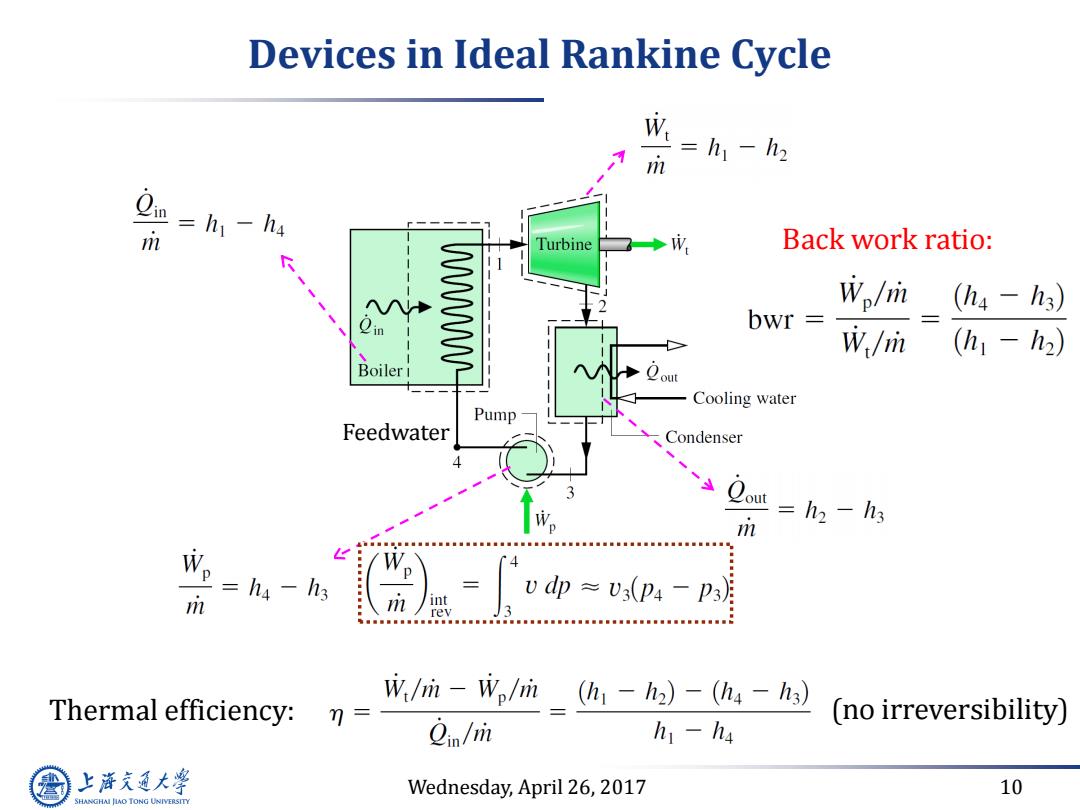
Devices in Ideal Rankine Cycle W=h一h m m =h1-h4 Turbine ◆成 Back work ratio: WWWWL Wo/m (hs-h3) bwr W/m (h1-h2) Boiler 1 Cooling water Pump Feedwater Condenser m =h2 -h3 =ha -h3 m /int Vdp≈V3(p4-p3月 rev Thermal efficiency: W/ri-Wplrin (h-h2)-(h4 -h3) 7= (no irreversibility) 2in/m h1-h4 上游充通大 Wednesday,April 26,2017 10 SHANGHAI JIAO TONG UNIVERSITY
Wednesday, April 26, 2017 10 Devices in Ideal Rankine Cycle Feedwater Thermal efficiency: Back work ratio: (no irreversibility)